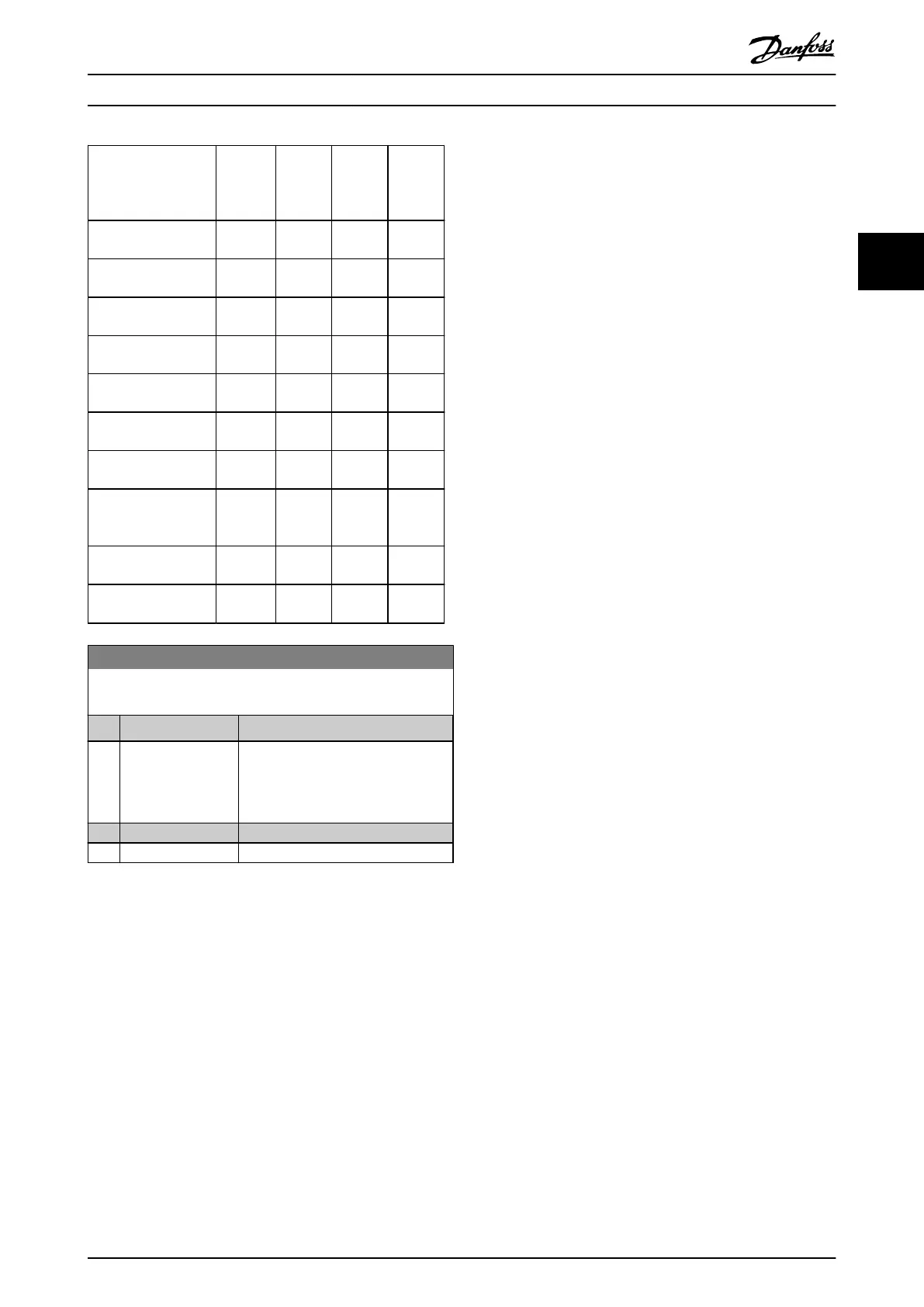
Parameter 1-10 Motor
Construction
[0]
Asynchro
-
nous
[1] PM
Motor
non-
salient
[2] PM
Motor
Salient
IPM
[3]
SynRM
Motor
Parameter 4-14 Motor
Speed High Limit [Hz]
x x x x
Parameter 4-16 Torque
Limit Motor Mode
x x x x
Parameter 4-17 Torque
Limit Generator Mode
x x x x
Parameter 4-18 Current
Limit
x x x x
Parameter 4-19 Max
Output Frequency
x x x x
Parameter 4-58 Missing
Motor Phase Function
x – x x
Parameter 14-40 VT
Level
x – – –
Parameter 14-41 AEO
Minimum Magneti-
sation
x – – –
Parameter 14-42 Minim
um AEO Frequency
x – – –
Parameter 14-43 Motor
Cosphi
x – – –
1-10 Motor Construction
Select the motor construction type.
Option: Function:
[0] * Asynchron For asynchronous motors.
[1] PM, non salient SPM For permanent magnet (PM) motors.
PM motors are divided into 2 groups,
with either surface-mounted (non-
salient) or interior (salient) magnets.
[2] PM, salient IPM
[5] SynRM
3.3.3 Asynchronous Motor Set-up
Enter the following motor data. Find the information on
the motor nameplate.
1. Parameter 1-20 Motor Power [kW] or
parameter 1-21 Motor Power [HP].
2. Parameter 1-22 Motor Voltage.
3. Parameter 1-23 Motor Frequency.
4. Parameter 1-24 Motor Current.
5. Parameter 1-25 Motor Nominal Speed.
For optimum performance in VVC
+
mode, extra motor data
is required to set up the following parameters. Find the
data in the motor datasheet (this data is typically not
available on the motor nameplate). Run a complete
automatic motor adaptation (AMA) using
parameter 1-29 Automatic Motor Adaptation (AMA) [1]
Enable Complete AMA or enter the parameters manually.
Parameter 1-36 Iron Loss Resistance (Rfe) is always entered
manually.
1. Parameter 1-30 Stator Resistance (Rs).
2. Parameter 1-31 Rotor Resistance (Rr).
3. Parameter 1-33 Stator Leakage Reactance (X1).
4. Parameter 1-34 Rotor Leakage Reactance (X2).
5. Parameter 1-35 Main Reactance (Xh).
6. Parameter 1-36 Iron Loss Resistance (Rfe).
Application-specic adjustment when running VVC
+
VVC
+
is the most robust control mode. In most situations,
it provides optimum performance without further
adjustments. Run a complete AMA for best performance.
3.3.4 PM Motor Set-up
This section describes how to set up a PM motor.
Initial programming steps
To activate PM motor operation, select [1] PM, non-salient
SPM or [2] PM, salient IPM in parameter 1-10 Motor
Construction.
Parameter Description Programming Guide
MG20OB02 Danfoss A/S © 05/2018 All rights reserved. 43
3 3

 Loading...


