VT characteristics
Variable torque characteristics used for pumps and fans.
VVC
+
If compared with standard voltage/frequency ratio control,
voltage vector control (VVC
+
) improves the dynamics and
the stability, both when the speed reference is changed
and in relation to the load torque.
60° AVM
60° asynchronous vector modulation
(parameter 14-00 Switching Pattern).
Power factor
The power factor is the relation between I
1
and I
RMS
.
Power factor =
3xUxI
1
cosϕ
3xUxI
RMS
The power factor for 3-phase control:
Power factor =
I1xcosϕ1
I
RMS
=
I
1
I
RMS
sincecosϕ1 = 1
The power factor indicates to which extent the frequency
converter imposes a load on the mains supply.
The lower the power factor, the higher the I
RMS
for the
same kW performance.
I
RMS
=
I
1
2
+ I
5
2
+ I
7
2
+ .. + I
n
2
In addition, a high power factor indicates that the dierent
harmonic currents are low.
The DC coils in the frequency converters produce a high
power factor, which minimizes the imposed load on the
mains supply.
Target position
The nal target position specied by positioning
commands. The prole generator uses this position to
calculate the speed prole.
Commanded position
The actual position reference calculated by the prole
generator. The frequency converter uses the commanded
position as setpoint for position PI.
Actual position
The actual position from an encoder, or a value that the
motor control calculates in open loop. The frequency
converter uses the actual position as feedback for position
PI.
Position error
Position error is the dierence between the actual position
and the commanded position. The position error is the
input for the position PI controller.
Position unit
The physical unit for position values.
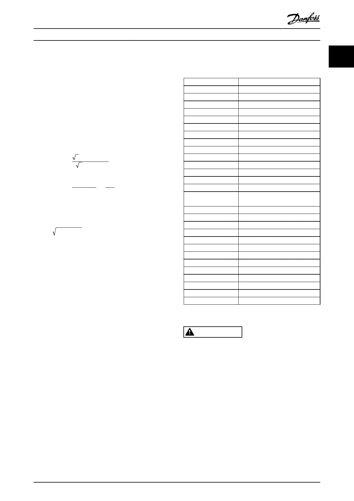
1.7
Abbreviations, Symbols, and
Conventions
°C
Degrees Celsius
°F
Degrees Fahrenheit
AC Alternating current
AEO Automatic energy optimization
AWG American wire gauge
AMA Automatic motor adaptation
DC Direct current
EMC Electro magnetic compatibility
ETR Electronic thermal relay
f
M,N
Nominal motor frequency
FC Frequency converter
I
INV
Rated inverter output current
I
LIM
Current limit
I
M,N
Nominal motor current
I
VLT,MAX
Maximum output current
I
VLT,N
Rated output current supplied by the
frequency converter
IP Ingress protection
LCP Local control panel
MCT Motion control tool
n
s
Synchronous motor speed
P
M,N
Nominal motor power
PELV Protective extra low voltage
PCB Printed circuit board
PM Motor Permanent magnet motor
PWM Pulse width modulation
RPM Revolutions per minute
Regen Regenerative terminals
T
LIM
Torque limit
U
M,N
Nominal motor voltage
1.8 Safety
WARNING
HIGH VOLTAGE
Frequency converters contain high voltage when
connected to AC mains input, DC supply, or load sharing.
Failure to perform installation, start-up, and maintenance
by qualied personnel can result in death or serious
injury.
•
Only qualied personnel must perform instal-
lation, start-up, and maintenance.
•
Before performing any service or repair work,
use an appropriate voltage measuring device to
make sure that there is no remaining voltage on
the frequency converter.
Introduction Programming Guide
MG20OB02 Danfoss A/S © 05/2018 All rights reserved. 7
1 1

 Loading...


