1.9 Electrical Wiring
1.9.1 Electrical Wiring - Control Cables
*
91 (L1)
92 (L2)
93 (L3)
PE
88 (-)
89 (+)
50 (+10 V OUT)
53 (A IN)
54 (A IN)
55 (COM A IN)
0/4-20 mA
12 (+24 V OUT)
13 (+24 V OUT)
18 (D IN)
20 (COM D IN)
15 mA 200 mA
(U) 96
(V) 97
(W) 98
(PE) 99
(COM A OUT) 39
(A OUT) 42
0/4-20 mA
03
0-10 V DC
+10 V DC
0-10 V DC
0/4-20 mA
240 V AC, 2 A
24 V DC
02
01
05
04
06
240 V AC, 2 A
24 V (NPN)
0 V (PNP)
0 V (PNP)
24 V (NPN)
19 (D IN)
24 V (NPN)
0 V (PNP)
27
24V
0V
(D IN/OUT)
0 V (PNP)
24 V (NPN)
(D IN/OUT)
0V
24V
29
24 V (NPN)
0 V (PNP)
0 V (PNP)
24 V (NPN)
33 (D IN)
32 (D IN)
1 2
ON
S201
ON
21
S202
ON=0-20 mA
OFF=0-10 V
95
400 V AC, 2 A
P 5-00
(R+) 82
(R-) 81
37 (D IN)
+ - + -
e30be257.11
(P RS485) 68
(N RS485) 69
(COM RS485) 61
0 V
5V
S801
RS485
RS485
21
ON
S801
3-phase
power
input
DC bus
Switch mode
power supply
Motor
Analog output
Interface
relay1
relay2
ON=Terminated
OFF=Open
Brake
resistor
(NPN) = Sink
(PNP) = Source
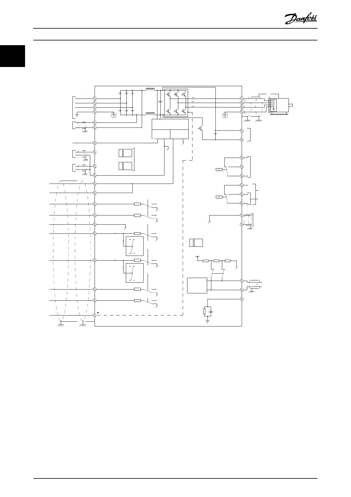
Illustration 1.2 Basic Wiring Schematic Drawing
A = Analog, D = Digital
Terminal 37 is used for Safe Torque O. For Safe Torque O installation instructions, refer to the VLT
®
Frequency Converters -
Safe Torque O Operating Instructions.
* Terminal 37 is not included in FC 202 (except enclosure size A1). Relay 2 and terminal 29 have no function in VLT
®
AQUA
Drive FC 202.
Long control cables and analog signals may in rare cases,
and depending on installation, result in 50/60 Hz ground
loops due to noise from mains supply cables.
If this occurs, it may be necessary to break the shield or
insert a 100 nF capacitor between shield and enclosure.
Connect the digital and analog inputs and outputs
separately to the common inputs (terminals 20, 55, and 39)
of the frequency converter to avoid ground currents from
both groups to aect other groups. For example, switching
on the digital input may disturb the analog input signal.
Introduction
VLT
®
AQUA Drive FC 202
10 Danfoss A/S © 05/2018 All rights reserved. MG20OB02
11

 Loading...


