3.24 Parameters 27-** Cascade CTL Option
Parameter group 27-** Cascade CTL Option is available if 1
of the following conditions is met:
•
VLT
®
Extended Cascade Controller MCO 101 is
installed.
•
VLT
®
Advanced Cascade Controller MCO 102 is
installed.
•
The frequency converter was ordered with the
type code LXX1.
Relay wiring conguration using MCO 101 or MCO 102
For a detailed description of commissioning for mixed
pump and master/slave applications (using relay
operation), refer to VLT
®
Cascade Controller Options MCO
101/102 Operating Instructions.
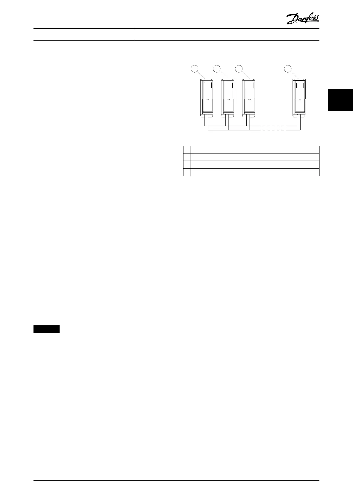
Serial communication wiring conguration
The serial communication wiring conguration supports
the master/slave cascade controller set-up controlling up to
8 pumps in total.
At least 1 of the frequency converters in the set-up must
have parameter group 27-** Cascade CTL Option enabled.
That enables option Modbus CASCADE Master in
parameter 8-30 Protocol.
The frequency converter with the lowest address and the
cascade controller capability is set as the primary master.
The remaining frequency converters must be addressed
with a unique address or forward-running number.
For slave frequency converters, option Modbus RTU in
parameter 8-30 Protocol has to be set. Reaction at
communication loss can be set in parameter 8-03 Control
Timeout Time and parameter 8-04 Control Timeout Function.
Apply this setting to all frequency converters in the
system.
This
conguration only supports the master/slave mode.
NOTICE
Terminate the RS485 bus with a resistor at both ends.
For this purpose, set switch S801 on the control card to
ON.
68 69
1 2 3 4
68 69 68 69 68 69
e30bg296.10
1 Primary master 1
2 Slave 1
3 Slave 2
4 Slave X (up to 7 slaves)
Illustration 3.95 Serial Communication Wiring
3.24.1 Master/Slave Conguration
The master/slave cascade control mode oers the best
performance, the most precise control, and maximum
energy savings. This mode controls multiple equally sized
pumps in parallel, running all pumps at the same speed
and stages the pumps on and o according to system
requirements.
Compared to the closed-loop cascade control, staging and
destaging decisions are made based on the speed
calculated by frequency converters instead of feedback.
Set the stage-on and stage-o speed according to the
system requirements to obtain the highest energy saving.
In the master/slave conguration, the master frequency
converter is running in closed loop, and the slave
frequency converters are running in open loop. All slave
frequency converters are connected to mains and the
motors in the same way as the master frequency converter.
In this conguration, each pump is controlled by a
frequency converter. All pumps and frequency converters
must be of the same size.
3.24.2 Mixed Pump Conguration
This conguration combines some of the benets of the
master/slave conguration with some of the initial cost
savings of the xed speed conguration. Use this congu-
ration when the extra capacity of the xed pumps is rarely
needed.
The mixed pump conguration supports a mix of variable
speed pumps connected to the frequency converters with
extra xed speed pumps. The variable speed pumps are
staged on and destaged rst based on the frequency
converter speed. The xed speed pumps are then staged
on last and destaged last based on the feedback pressure.
Parameter Description Programming Guide
MG20OB02 Danfoss A/S © 05/2018 All rights reserved. 223
3 3

 Loading...


