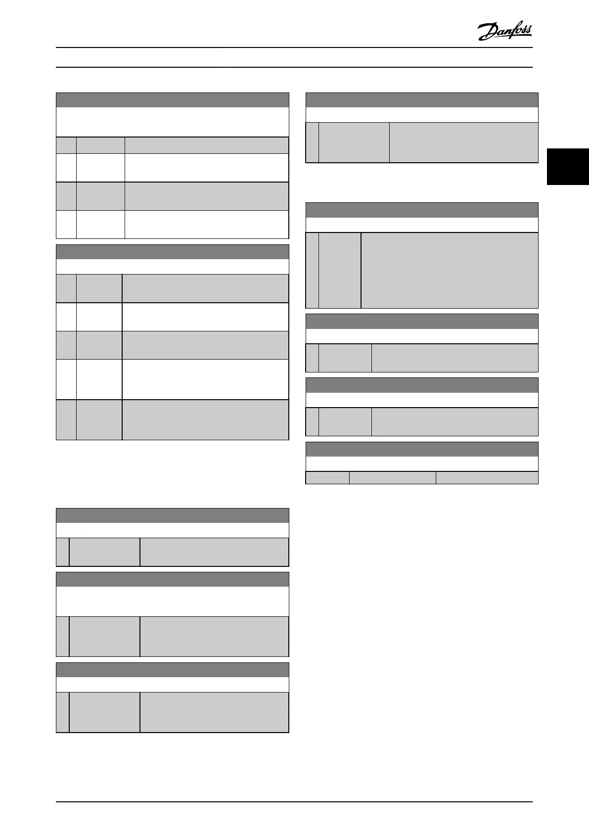
8-55 Set-up Select
Select the trigger for the set-up selection.
Option: Function:
[0] Digital input A digital input triggers the set-up selection.
[1] Bus A serial communication port or the eldbus
triggers the set-up selection.
[2] Logic AND The eldbus/serial communication port and a
digital input trigger the set-up selection.
[3] * Logic OR The eldbus/serial communication port or a
digital input triggers the set-up selection.
8-56 Preset Reference Select
Option: Function:
Select the trigger for the preset reference
selection.
[0] Digital
input
A digital input triggers the preset reference
selection.
[1] Bus A serial communication port or the eldbus
triggers the preset reference selection.
[2] Logic AND The eldbus/serial communication port and a
digital input trigger the preset reference
selection.
[3] * Logic OR The eldbus/serial communication port or a
digital input triggers the preset reference
selection.
3.9.6 8-8* FC Port Diagnostics
These parameters are used for monitoring the bus
communication via the frequency converter port.
8-80 Bus Message Count
Range: Function:
0* [0 - 4294967295 ] This parameter shows the number of
valid telegrams detected on the bus.
8-81 Bus Error Count
Array [6]
Range: Function:
0* [0 - 4294967295 ] This parameter shows the number of
telegrams with faults (for example CRC
fault) detected on the bus.
8-82 Slave Message Rcvd
Range: Function:
0* [0 - 4294967295 ] This parameter shows the number of
valid telegrams addressed to the slave
sent by the frequency converter.
8-83 Slave Error Count
Range: Function:
0* [0 - 4294967295 ] This parameter shows the number of
error telegrams, which are not executed
by the frequency converter.
3.9.7 8-9* Bus Jog
8-94 Bus Feedback 1
Range: Function:
0* [-200 -
200 ]
Write feedback to this parameter via the serial
communication port or eldbus option. Select
this parameter as a feedback source in
parameter 20-00 Feedback 1 Source,
parameter 20-03 Feedback 2 Source, or
parameter 20-06 Feedback 3 Source.
8-95 Bus Feedback 2
Range: Function:
0* [-200 - 200 ] See parameter 8-94 Bus Feedback 1 for further
details.
8-96 Bus Feedback 3
Range: Function:
0* [-200 - 200 ] See parameter 8-94 Bus Feedback 1 for further
details.
8-97 Response Error Codes
Range: Function:
0* [0 - 0 ]
3.10 Parameters 9-** PROFIBUS
For PROFIBUS parameter descriptions, see the VLT
®
PROFIBUS DP MCA 101 Programming Guide.
Parameter Description Programming Guide
MG20OB02 Danfoss A/S © 05/2018 All rights reserved. 109
3 3

 Loading...


