3.17 Parameters 20-** FC Closed Loop
Closed-loop PID
This parameter group is used for conguring the closed-
loop PID controller that controls the output frequency of
the frequency converter.
Closed-loop DRC
DRC (Disturbance Rejection Control) improves adherence
to the desired process control setpoint (for example,
desired water pressure) by responding more rapidly to
both incidental load disturbances and changes in setpoint.
DRC reacts rapidly to ensure the system quickly returns to
the desired pressurization. This improved regulation
ensures process consistency and reduces oscillations that
may adversely aect mechanical infrastructure. DRC relies
on a proprietary control algorithm that compensates for
any behavior observed as deviating from the expected
behavior based on the basic physical model generated by
DRC Identify. DRC Control thus intrinsically depends on the
system characteristics measured by
parameter 20-79 Autotuning, when it is set to SPC. The DRC
controller is then engaged based on the measured system
information retrieved during the auto-tuning process. DRC
responsiveness is initially set to a value that depends on
whether the relevant system is dened as "normal"
(default) or "fast", which can be modied in
parameter 20-71 Controller Performance. A fast system
might be a well-dened irrigation system with short ramp
times that requires rapid response to changes in desired
water pressure or opened valves.
NOTICE
DRC is not yet recommended for usage in systems that
utilize Cascade Controller functionality (for example,
municipal water distribution systems).
3.17.1 20-0* Feedback
This parameter group is used to congure the feedback
signal for the closed-loop PID controller. Whether the
frequency converter is in closed-loop mode or open-loop
mode, the feedback signals can be shown on the LCP
display. It can also be used to control a frequency
converter analog output, and be transmitted over various
serial communication protocols.
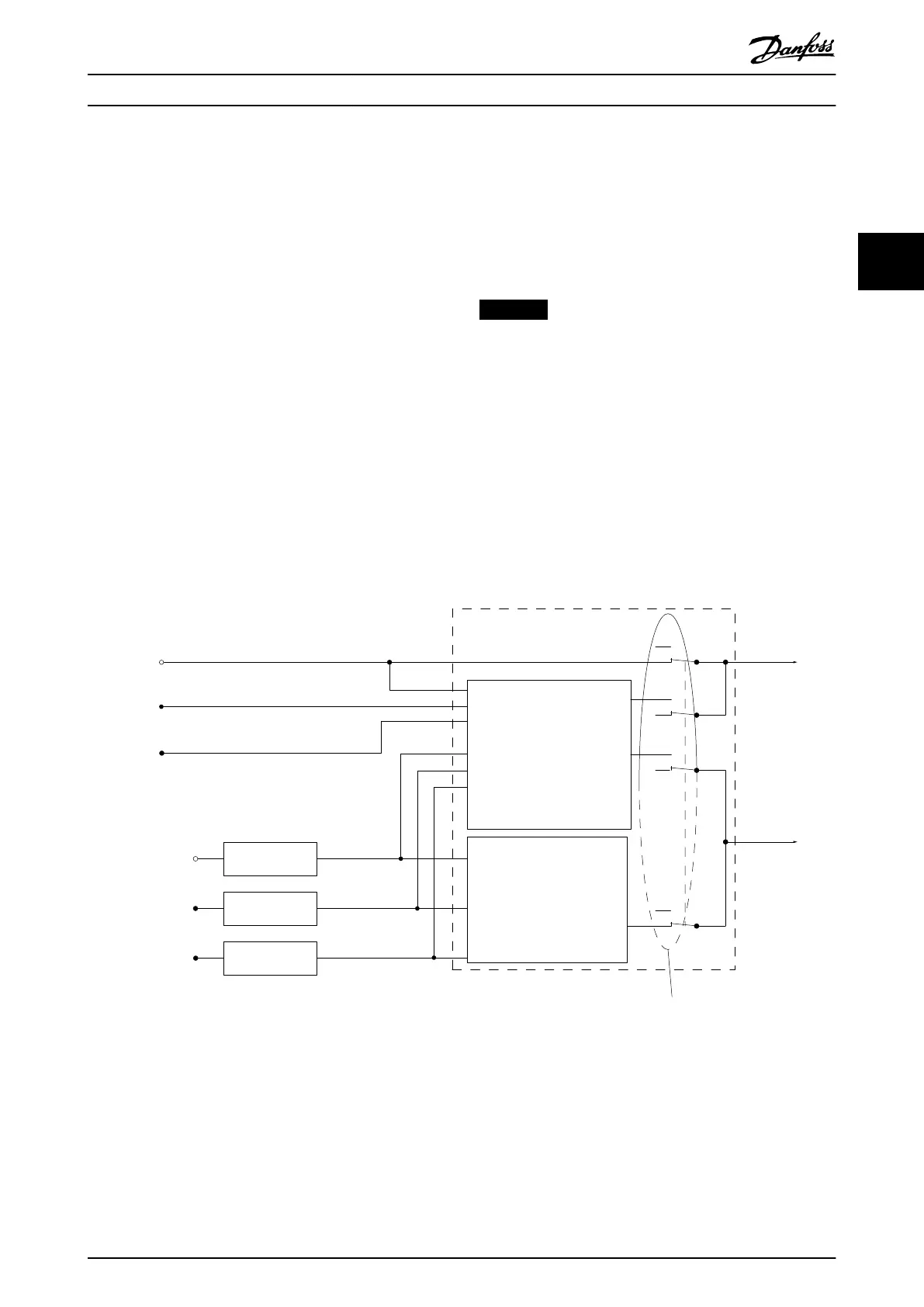
Setpoint 1
P 20-21
Setpoint 2
P 20-22
Setpoint 3
P 20-23
Feedback 1 Source
P 20-00
Feedback 2 Source
P 20-03
Feedback 3 Source
P 20-06
Feedback conv.
P 20-01
Feedback conv.
P 20-04
Feedback conv.
P 20-07
Feedback 1
Feedback 2
Feedback 3
Feedback
Feedback Function
P 20-20
Multi setpoint min.
Multi setpoint max.
Feedback 1 only
Feedback 2 only
Feedback 3 only
Sum (1+2+3)
Dierence (1-2)
Average (1+2+3)
Minimum (1|2|3)
Maximum (1|2|3)
Setpoint to
Reference
Handling
0%
0%
0%
0%
130BA354.12
Illustration 3.60 Input Signals in Closed-loop PID Controller
Parameter Description Programming Guide
MG20OB02 Danfoss A/S © 05/2018 All rights reserved. 159
3 3

 Loading...


