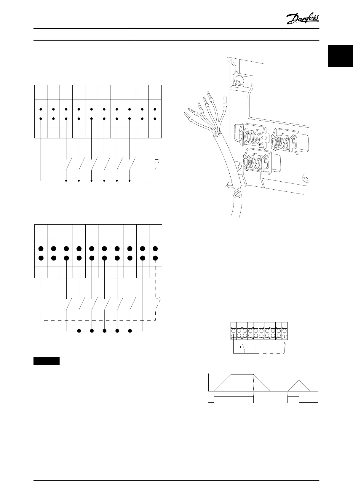
Input polarity of control terminals
12 13 18 19 27 29 32 33 20 37
+24 VDC
0 VDC
130BT106.10
PNP (Source)
Digital input wiring
Illustration 1.3 PNP (Source)
NPN (Sink)
Digital input wiring
12 13 18 19 27 29 32 33 20 37
+24 VDC
0 VDC
130BT107.11
Illustration 1.4 NPN (Sink)
NOTICE
Control cables must be shielded/armored.
See the section Grounding of Shielded Control Cables in the
design guide for the correct termination of control cables.
Illustration 1.5 Grounding of Shielded/Armored Control Cables
1.9.2 Start/Stop
Terminal 18 = Parameter 5-10 Terminal 18 Digital Input [8]
Start.
Terminal 27 = Parameter 5-12 Terminal 27 Digital Input [0]
No operation (default [2] Coast inverse).
Terminal 37 = Safe Torque O (where available).
12 13 18 37
130BA155.12
322719 29 33 20
P 5-12 [0]
P 5-10 [8]
Start/Stop
+24V
Speed
Safe Stop
Start/Stop
[18]
Illustration 1.6 Start/Stop
Introduction Programming Guide
MG20OB02 Danfoss A/S © 05/2018 All rights reserved. 11
1 1

 Loading...


