[65] Reset Counter
B
Input for reset of counter B.
[66] Sleep Mode Forces the frequency converter into sleep
mode (see parameter group 22-4* Sleep
Mode). Reacts on the rising edge of signal
applied.
[78] Reset
Preventive
Maintenance
Word
Resets all data in
parameter 16-96 Maintenance Word to 0.
[80] PTC Card1 All digital inputs can be set to [80] PTC Card
1. However, only 1 digital input must be set
to this option.
[85] Latched
Pump Derag
Starts deragging.
Options [120]–[138] are related to the cascade controller
functionality. For more information, see parameter group
25-** Cascade Controller.
[120] Lead Pump
Start
Starts/stops the lead pump (controlled by
the frequency converter). A start also
requires applying a system start signal, for
example to 1 of the digital inputs set for [8]
Start.
[121] Lead Pump
Alternation
Forces alternation of the lead pump in a
cascade controller. Set parameter 25-50 Lead
Pump Alternation to either [2] At Command
or [3] At Staging or At Command.
Parameter 25-51 Alternation Event can be set
to any of the 4 options.
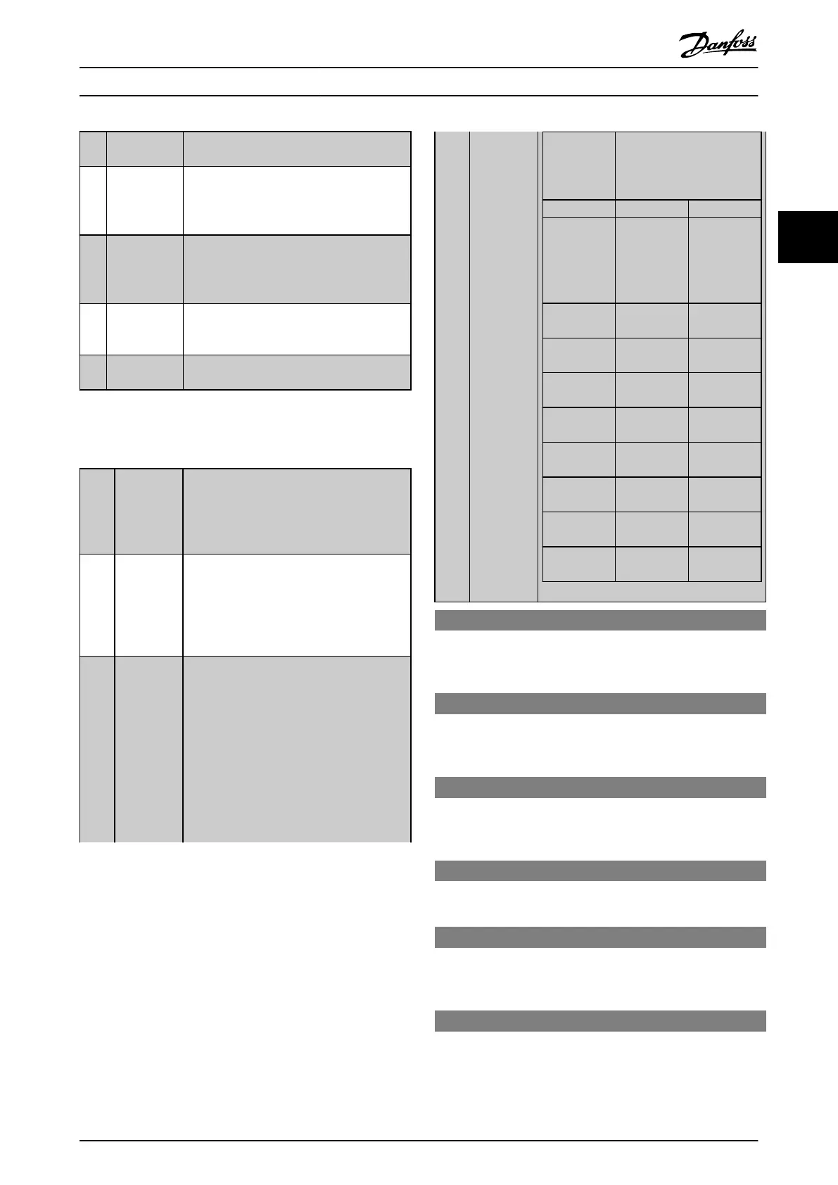
[130
-
138]
Pump1
Interlock -
Pump9
Interlock
The function depends on the setting in
parameter 25-06 Number of Pumps. If set to
[0] No, then Pump1 refers to the pump
controlled by relay1 and so on. If set to [1]
Yes, Pump1 refers to the pump controlled by
the frequency converter only (without any of
the built-in relays involved) and Pump2 to
the pump controlled by relay1. Variable
speed pump (lead) cannot be interlocked in
the basic cascade controller.
See Table 3.14.
Setting in
parameter
group 5-1*
Digital Inputs
Setting in
parameter 25-06 Number of
Pumps
[0] No [1] Yes
[130] Pump1
Interlock
Controlled by
relay1
(only if not
lead pump)
Controlled by
frequency
converter
(cannot be
interlocked)
[131] Pump2
Interlock
Controlled by
relay2
Controlled by
relay1
[132] Pump3
Interlock
Controlled by
relay3
Controlled by
relay2
[133] Pump4
Interlock
Controlled by
relay4
Controlled by
relay3
[134] Pump5
Interlock
Controlled by
relay5
Controlled by
relay4
[135] Pump6
Interlock
Controlled by
relay6
Controlled by
relay5
[136] Pump7
Interlock
Controlled by
relay7
Controlled by
relay6
[137] Pump8
Interlock
Controlled by
relay8
Controlled by
relay7
[138] Pump9
Interlock
Controlled by
relay9
Controlled by
relay8
5-10 Terminal 18 Digital Input
The parameter contains all options and functions listed in
parameter group 5-1* Digital Inputs except for option [32] Pulse
input.
5-11 Terminal 19 Digital Input
The parameter contains all options and functions listed in
parameter group 5-1* Digital Inputs except for option [32] Pulse
input.
5-12 Terminal 27 Digital Input
The parameter contains all options and functions listed in
parameter group 5-1* Digital Inputs except for option [32] Pulse
input.
5-13 Terminal 29 Digital Input
The parameter contains all options and functions listed in
parameter group 5-1* Digital Inputs.
5-14 Terminal 32 Digital Input
The parameter contains all options and functions listed in
parameter group 5-1* Digital Inputs except for option [32] Pulse
input.
5-15 Terminal 33 Digital Input
The parameter contains all options and functions listed in
parameter group 5-1* Digital Inputs.
Parameter Description Programming Guide
MG20OB02 Danfoss A/S © 05/2018 All rights reserved. 79
3 3

 Loading...


