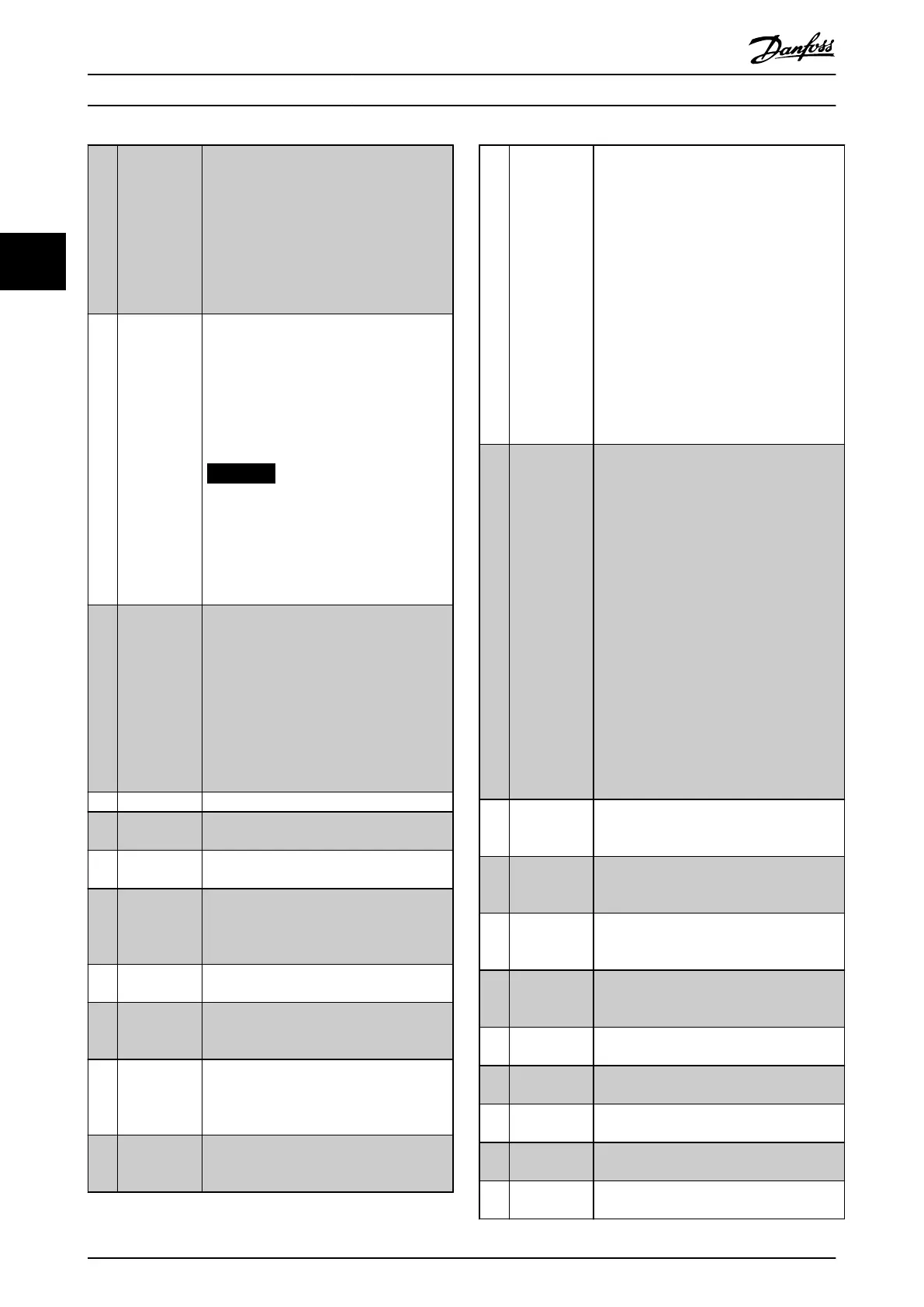
[19] Freeze ref Freezes the actual reference. The frozen
reference is now the point of enable/
condition for speed up and speed down to
be used. If speed up/speed down is used,
the speed change always follows ramp 2
(parameter 3-51 Ramp 2 Ramp Up Time and
parameter 3-52 Ramp 2 Ramp Down Time) in
the range 0–parameter 3-03 Maximum
Reference.
[20] Freeze output Freezes the actual motor frequency (Hz). The
frozen motor frequency is now the point of
enable/condition for speed up and speed
down to be used. If speed up/speed down is
used, the speed change always follows ramp
2 (parameter 3-51 Ramp 2 Ramp Up Time and
parameter 3-52 Ramp 2 Ramp Down Time) in
the range 0–parameter 1-23 Motor Frequency.
NOTICE
When [20] Freeze output is active, the
frequency converter cannot be
stopped via a low [13] Start signal.
Stop the frequency converter via a
terminal programmed for [2] Coast
inverse or [3] Coast and reset, inverse.
[21] Speed up For digital control of the speed up/speed
down (motor potentiometer). Activate this
function by selecting either [19] Freeze
reference or [20] Freeze output. When [21]
Speed up is activated for less than 400 ms,
the resulting reference is increased by 0.1%.
If [21] Speed up is activated for more than
400 ms, the resulting reference ramps
according to ramp 1 in parameter 3-41 Ramp
1 Ramp Up Time.
[22] Speed down Same as [21] Speed up.
[23] Set-up select
bit 0
Selects 1 of the 4 set-ups. Set
parameter 0-10 Active Set-up to Multi Set-up.
[24] Set-up select
bit 1
Same as [23] Set-up select bit 0.
(Default digital input 32).
[32] Pulse input Select [32] Pulse input when using a pulse
sequence as either reference or feedback.
Scaling is done in parameter group 5-5* Pulse
Input.
[34] Ramp bit 0 Select which ramp to use. Logic 0 selects
ramp 1 while logic 1 selects ramp 2.
[36] Mains failure
inverse
Activates parameter 14-10 Mains Failure.
Mains failure inverse is active in the logic 0
situation.
[42] Ref source bit
0
An active input in bit 0 selects AI54 as the
reference source (see parameter group 3-1*
References, option [35] Digital input select).
An inactive input selects AI53.
[51] Hand/Auto
Start
Selects hand or auto start. High signal
selects auto on only, Low signal selects hand
on only.
[52] Run
Permissive
The input terminal, for which the [52] Run
Permissive has been programmed, must be
logic 1 before a start command can be
accepted. Run permissive has a logic AND
function related to the terminal, which is
programmed for [8] Start, [14] Jog, or [20]
Freeze Output. To start running the motor,
both conditions must be fullled. If [52] Run
Permissive is programmed on multiple
terminals, it only has to be logic 1 on 1 of
the terminals to carry out the function. The
digital output signal for run request ([8]
Start, [14] Jog, or [20] Freeze output)
programmed in parameter group 5-3* Digital
Outputs, or parameter group 5-4* Relays, is
not aected by [52] Run Permissive.
[53] Hand start A signal applied puts the frequency
converter into hand-on mode as if [Hand
On] has been pressed and a normal stop
command is overridden. If disconnecting the
signal, the motor stops. To make any other
start commands valid, assign another digital
input to [54] Auto Start and apply a signal to
this. [Hand On] and [Auto On] have no
impact. [O] overrides local start and auto
start. Press either [Hand On] or [Auto On] to
make local start and auto start active again.
If there is no signal on neither [53] Hand
start nor [54] Auto start, the motor stops
regardless of any normal start command
applied. If a signal is applied to both [53]
Hand start and [54] Auto start, the function is
auto start. If pressing [O], the motor stops
regardless of signals on [53] Hand start and
[54] Auto start.
[54] Auto start A signal applied puts the frequency
converter into auto-on mode as if [Auto On]
has been pressed. See also [53] Hand Start.
[55] DigiPot
Increase
Uses the input as an increase signal to the
digital potentiometer function described in
parameter group 3-9* Digital Pot.Meter.
[56] DigiPot
Decrease
Uses the input as a decrease signal to the
digital potentiometer function described in
parameter group 3-9* Digital Pot.Meter.
[57] DigiPot Clear Uses the input to clear the digital potenti-
ometer reference described in parameter
group 3-9* Digital Pot.Meter.
[60] Counter A
(up)
(Terminal 29 or 33 only) Input for increment
counting in the SLC counter.
[61] Counter A
(down)
(Terminal 29 or 33 only) Input for decrement
counting in the SLC counter.
[62] Reset Counter
A
Input for reset of counter A.
[63] Counter B
(up)
(Terminal 29 and 33 only) Input for
increment counting in the SLC counter.
[64] Counter B
(down)
(Terminal 29 and 33 only) Input for
decrement counting in the SLC counter.
Parameter Description
VLT
®
AQUA Drive FC 202
78 Danfoss A/S © 05/2018 All rights reserved. MG20OB02
33

 Loading...


