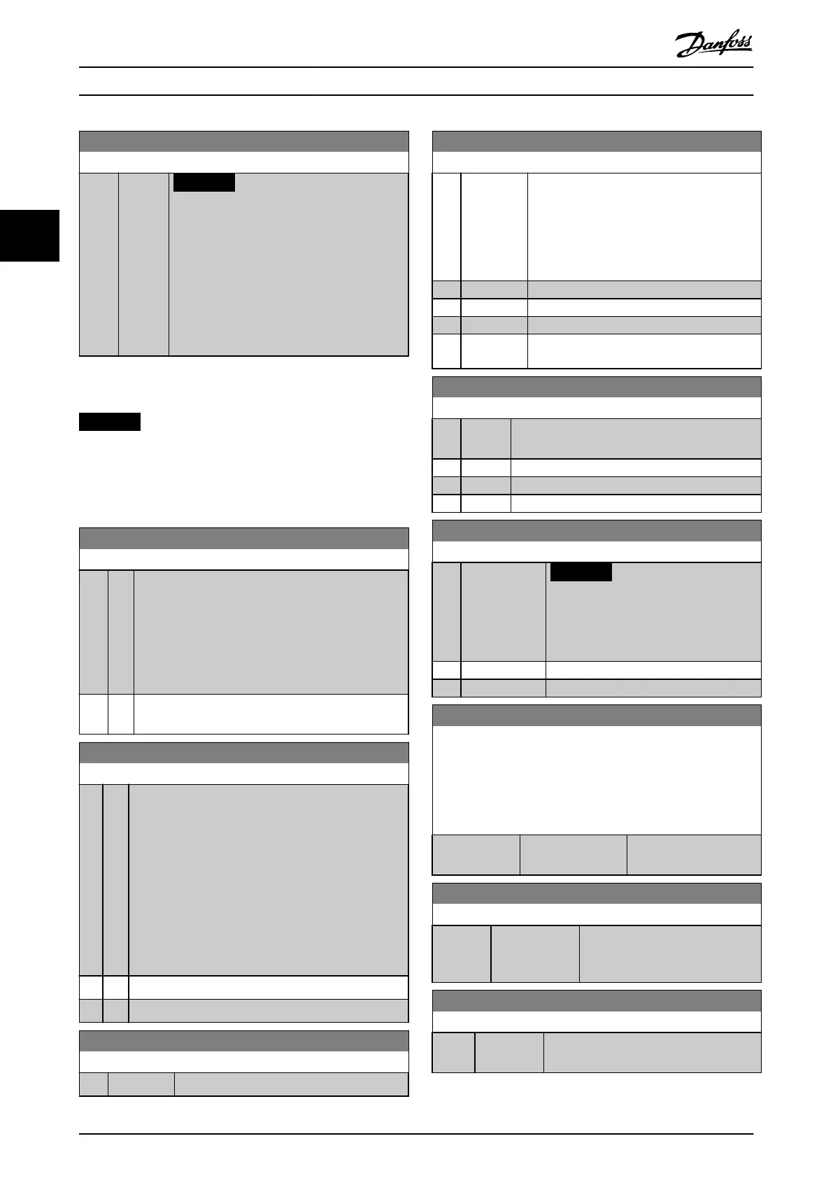
14-43 Motor Cosphi
Range: Function:
0.66
N/A*
[0.40 -
0.95
N/A]
NOTICE
This parameter is not active when
parameter 1-10 Motor Construction is set
to [1] PM, non-salient SPM.
The Cos(phi) setpoint is automatically set to
optimum AEO performance during AMA. Under
normal circumstances, do NOT alter this
parameter. However, in some situations it may
be necessary to enter a new value to ne-tune.
3.13.6 14-5* Environment
NOTICE
Perform a power cycle after changing any of the
parameters in parameter group 14-5* Environment.
These parameters help the frequency converter to operate
under special environmental conditions.
14-50 RFI Filter
Option: Function:
[0] O Select [0] O only when the frequency converter is
supplied from an isolated mains source, that is, IT
mains. In this mode, the internal RFI capacities (lter
capacitors) between chassis and the mains RFI lter
circuit is cut o to avoid damage to the DC link and
to reduce the ground capacity currents (according to
IEC 61800-3).
[1] * On Select [1] On to ensure that the frequency converter
complies with EMC standards.
14-51 DC-Link Compensation
Option: Function:
The rectied AC-DC voltage in the frequency converter's
DC link is associated with voltage ripples. These ripples
can increase in magnitude with increased load. These
ripples are undesirable because they can generate
current and torque ripples. A compensation method is
used to reduce these voltage ripples in the DC link. In
general, DC-link compensation is recommended for
most applications, but pay attention when operating in
eld weakening as it can generate speed oscillations at
the motor shaft. In eld weakening, turn o DC-link
compensation.
[0] O Disables DC-link compensation.
[1] On Enables DC-link compensation.
14-52 Fan Control
Option: Function:
Select the minimum speed of the main fan.
14-52 Fan Control
Option: Function:
[0] * Auto Select [0] Auto to run the fan only when the
internal temperature of the frequency
converter is in the range 35 °C (95 °F) to
approximately 55 °C (131 °F). The fan runs at
low speed at 35 °C (95 °F) and at full speed
at approximately 55 °C (131 °F).
[1] On 50%
[2] On 75%
[3] On 100%
[4] Auto (Low
temp env.)
14-53 Fan Monitor
Option: Function:
Select the frequency converter action if a fan
fault is detected.
[0] Disabled
[1] * Warning
[2] Trip
14-55 Output Filter
Option: Function:
NOTICE
This parameter cannot be adjusted
while the motor is running.
Select the type of output lter connected.
[0] * No Filter
[1] Sine-Wave Filter
14-56 Capacitance Output Filter
Enter the capacitance of the output lter. Find the value on the
lter label. For the compensation function of the LC lter in the
star connection, enter the per phase equivalent capacitance of
the lter (3 times the capacitance between 2 phases in the delta
connection).
Range: Function:
2.0 uF* [0.1 - 6500.0 uF] Enter the capacitance of
the output lter.
14-57 Inductance Output Filter
Range: Function:
7.000 mH* [0.001 - 65.000
mH]
Set the inductance of the output
lter. The value can be found on
the lter label.
14-58 Voltage Gain Filter
Range: Function:
100 %* [0 - 200 %] Select the gain applied to the voltage
when using an LC lter.
Parameter Description
VLT
®
AQUA Drive FC 202
138 Danfoss A/S © 05/2018 All rights reserved. MG20OB02
33

 Loading...


