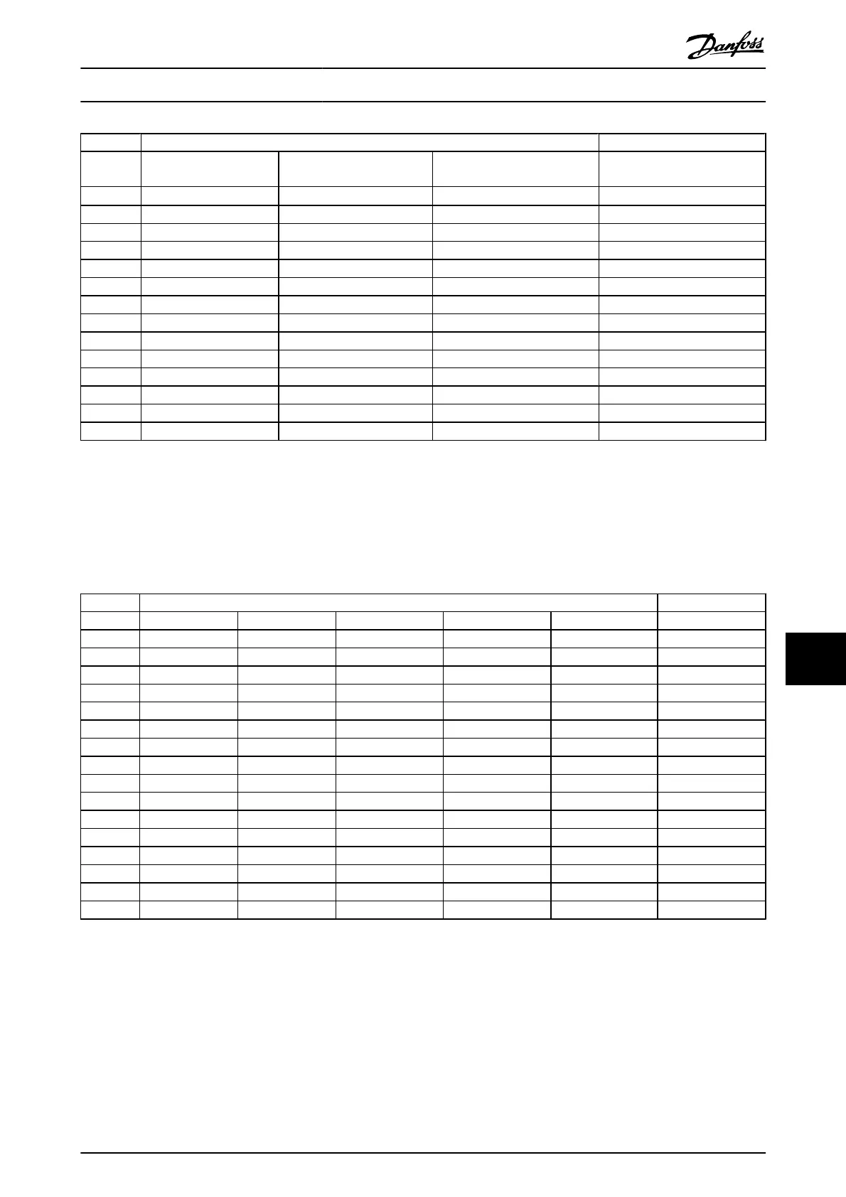
Recommended max. fuse
FC 300
Bussmann Littel fuse
Ferraz-
Shawmut
Ferraz-
Shawmut
[kW]
Type JFHR2
2)
JFHR2
JFHR2
4)
J
0.25-0.37
FWX-5 - - HSJ-6
0.55-1.1
FWX-10 - - HSJ-10
1.5
FWX-15 - - HSJ-15
2.2
FWX-20 - - HSJ-20
3.0
FWX-25 - - HSJ-25
3.7
FWX-30 - - HSJ-30
5.5
FWX-50 - - HSJ-50
7.5
FWX-60 - - HSJ-60
11
FWX-80 - - HSJ-80
15-18.5
FWX-125 - - HSJ-125
22
FWX-150 L25S-150 A25X-150 HSJ-150
30
FWX-200 L25S-200 A25X-200 HSJ-200
37
FWX-250 L25S-250 A25X-250 HSJ-250
Table 10.7 200-240V, Frame Sizes A, B, and C
1) KTS-fuses from Bussmann may substitute KTN for 240V frequency converters.
2) FWH-fuses from Bussmann may substitute FWX for 240V frequency converters.
3) A6KR fuses from FERRAZ SHAWMUT may substitute A2KR for 240V frequency converters.
4) A50X fuses from FERRAZ SHAWMUT may substitute A25X for 240V frequency converters.
Recommended max. fuse
FC 300 Bussmann Bussmann Bussmann Bussmann Bussmann Bussmann
[kW] Type RK1 Type J Type T Type CC Type CC Type CC
0.37-1.1 KTS-R-6 JKS-6 JJS-6 FNQ-R-6 KTK-R-6 LP-CC-6
1.5-2.2 KTS-R-10 JKS-10 JJS-10 FNQ-R-10 KTK-R-10 LP-CC-10
3 KTS-R-15 JKS-15 JJS-15 FNQ-R-15 KTK-R-15 LP-CC-15
4 KTS-R-20 JKS-20 JJS-20 FNQ-R-20 KTK-R-20 LP-CC-20
5.5 KTS-R-25 JKS-25 JJS-25 FNQ-R-25 KTK-R-25 LP-CC-25
7.5 KTS-R-30 JKS-30 JJS-30 FNQ-R-30 KTK-R-30 LP-CC-30
11 KTS-R-40 JKS-40 JJS-40 - - -
15 KTS-R-50 JKS-50 JJS-50 - - -
18 KTS-R-60 JKS-60 JJS-60 - - -
22 KTS-R-80 JKS-80 JJS-80 - - -
30 KTS-R-100 JKS-100 JJS-100 - - -
37 KTS-R-125 JKS-125 JJS-125 - - -
45 KTS-R-150 JKS-150 JJS-150 - - -
55 KTS-R-200 JKS-200 JJS-200 - - -
75 KTS-R-250 JKS-250 JJS-250 - - -
Table 10.8 380-500V, Frame Sizes A, B, and C
Specifications
VLT
®
AutomationDrive Operating
Instructions
MG.33.AJ.02 - VLT
®
is a registered Danfoss trademark 81
10 1