6. Press [OK] again for Fan Functions.
7. Press [OK] to select Broken Belt Function.
8.
Press [
▼
], to select [2] Trip.
If a broken fan-belt is detected, the frequency converter
trips.
Select Q1 My Personal Menu to show personal parameters
For example, an AHU or pump OEM may have pre-
programmed personal parameters to be in My Personal
Menu during factory commissioning to simplify on-site
commissioning/ne-tuning. These parameters are selected
in parameter 0-25 My Personal Menu. Up to 20 dierent
parameters can be programmed in this menu.
Select Changes Made to obtain information about:
•
The last 10 changes. Press [
▲
] and [
▼
] to scroll
between the last 10 changed parameters.
•
The changes made since default setting.
Loggings
Loggings show information about the display line
readouts. The information is shown as graphs.
Only display parameters selected in parameter 0-20 Display
Line 1.1 Small and parameter 0-24 Display Line 3 Large can
be viewed. Up to 120 samples can be stored in the
memory for later reference.
Quick Set-up
Ecient parameter set-up for HVAC applications
The parameters can easily be set up for most HVAC
applications only by using the Quick Set-up.
After pressing [Quick Menu], the dierent options in the
Quick Menu are listed. See also Illustration 2.19 and
Table 2.2 to Table 2.5.
Example of using the Quick Set-up
Setting the ramp-down time to 100 s:
1. Select Quick Set-up. Parameter 0-01 Language in
Quick Set-up appears.
2.
Press [
▼
] repeatedly until parameter 3-42 Ramp 1
Ramp Down Time appears with the default setting
of 20 s.
3. Press [OK].
4.
Press [
◀
] to highlight the third digit before the
comma.
5.
Change 0 to 1 by pressing [
▲
].
6.
Press [
▶
] to highlight the digit 2.
7.
Change 2 to 0 by pressing [
▼
].
8. Press [OK].
The new ramp-down time is now set to 100 s.
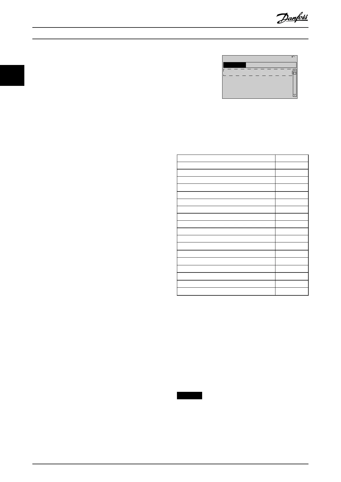
130BP064.10
Q1 My Personal Menu
Q2 Quick Setup
Q3 Function Setups
Q5 Changes Made
40.0% 4.84 A 1(1)
Quick Menus
Illustration 2.19 Quick Menu View
Access the 18 most important setup parameters of the
frequency converter via Quick Set-up. After programming,
the frequency converter is ready for operation. The 18
Quick Set-up parameters are shown in Table 2.1.
Parameter [Units]
Parameter 0-01 Language
Parameter 1-20 Motor Power [kW] [kW]
Parameter 1-21 Motor Power [HP] [Hp]
Parameter 1-22 Motor Voltage
1)
[V]
Parameter 1-23 Motor Frequency [Hz]
Parameter 1-24 Motor Current [A]
Parameter 1-25 Motor Nominal Speed [RPM]
Parameter 1-28 Motor Rotation Check [Hz]
Parameter 3-41 Ramp 1 Ramp Up Time [s]
Parameter 3-42 Ramp 1 Ramp Down Time [s]
Parameter 4-11 Motor Speed Low Limit [RPM] [RPM]
Parameter 4-12 Motor Speed Low Limit [Hz]
1)
[Hz]
Parameter 4-13 Motor Speed High Limit [RPM] [RPM]
Parameter 4-14 Motor Speed High Limit [Hz]
1)
[Hz]
Parameter 3-19 Jog Speed [RPM] [RPM]
Parameter 3-11 Jog Speed [Hz]
1)
[Hz]
Parameter 5-12 Terminal 27 Digital Input
Parameter 5-40 Function Relay
2)
Table 2.1 Quick Set-up Parameters
1) The information shown in the display depends on the selections
made in parameter 0-02 Motor Speed Unit and
parameter 0-03 Regional Settings. The default settings of
parameter 0-02 Motor Speed Unit and parameter 0-03 Regional
Settings depend on which region of the world the frequency
converter is supplied to, but can be reprogrammed as required.
2) Parameter 5-40 Function Relay is an array. Select between [0]
Relay1 or [1] Relay2. Standard setting is [0] Relay1 with the default
option [9] Alarm.
For detailed information about settings and programming,
see chapter 3 Parameter Descriptions.
NOTICE
If [0] No Operation is selected in parameter 5-12 Terminal
27 Digital Input, no connection to +24 V on terminal 27
is necessary to enable start.
If [2] Coast Inverse (factory default value) is selected in
parameter 5-12 Terminal 27 Digital Input, a connection to
+24 V is necessary to enable start.
How to Programme
VLT
®
HVAC Drive FC 102
18 Danfoss A/S © 10/2019 All rights reserved. M0010001
22
 Loading...


