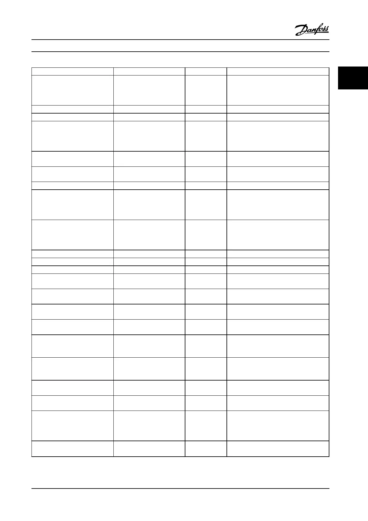
Parameter Range Default Function
1-37 d-axis Inductance (Ld) 0–1000 Size related Enter the value of the d-axis inductance.
Obtain the value from the permanent magnet
motor data sheet. The de-axis inductance
cannot be found by performing an AMA.
1-39 Motor Poles 2–100 4 Enter the number of motor pole.
1-40 Back EMF at 1000 RPM 10–9000 Size related Line-Line RMS back EMF voltage at 1000 RPM
1-73 Flying Start [0] Disabled
[1] Enabled
0
Select [1] Enable to enable the adjustable
frequency drive to catch a spinning motor,
e.g., in fan applications. When PM is selected,
Flying Start is enabled.
3-02 Minimum Reference -4999–4999 0 The minimum reference is the lowest value
obtainable by summing all references.
3-03 Maximum Reference -4999–4999 50 The maximum reference is the highest value
obtainable by summing all references.
3-10 Preset Reference -100–100% 0 Enter the setpoint.
3-41 Ramp 1 Ramp Up Time 0.05–3600.0 s Size related
Ramp-up time from 0 to rated 1-23 Motor
Frequency if Asynchron motor is selected;
ramp-up time from 0 to 1-25 Motor Nominal
Speed if PM motor is selected.
3-42 Ramp 1 Ramp Down Time 0.05–3600.0 s Size related
Ramp-down time from rated 1-23 Motor
Frequency to 0 if Asynchron motor is selected;
ramp-down time from 1-25 Motor Nominal
Speed to 0 if PM motor is selected.
4-12 Motor Speed Low Limit [Hz] 0.0–400 Hz 0.0 Hz Enter the minimum limit for low speed.
4-14 Motor Speed High Limit [Hz] 0–400 Hz 65 Hz Enter the minimum limit for high speed.
4-19 Max Output Frequency 0–400 Size related Enter the maximum output frequency value.
6-20 Terminal 54 Low Voltage 0–10 V 0.07 V Enter the voltage that corresponds to the low
reference value.
6-21 Terminal 54 High Voltage 0–10 V 10 V Enter the voltage that corresponds to the low
high reference value.
6-22 Terminal 54 Low Current 0–20 mA 4 Enter the current that corresponds to the high
reference value.
6-23 Terminal 54 High Current 0–20 mA 20 Enter the current that corresponds to the high
reference value.
6-24 Terminal 54 Low Ref./Feedb.
Value
-4999–4999 0 Enter the feedback value that corresponds to
the voltage or current set in 6-20 Terminal 54
Low Voltage/6-22 Terminal 54 Low Current
6-25 Terminal 54 High Ref./Feedb.
Value
-4999–4999 50 Enter the feedback value that corresponds to
the voltage or current set in 6-21 Terminal 54
High Voltage/6-23 Terminal 54 High Current
6-26 Terminal 54 Filter Time
Constant
0–10 s 0.01 Enter the filter time constant.
6-29 Terminal 54 mode [0] Current
[1] Voltage
1 Select if terminal 54 is used for current or
voltage input.
20-81 PI Normal/ Inverse Control [0] Normal
[1] Inverse
0
Select [0] Normal to set the process control to
increase the output speed when the process
error is positive. Select [1] Inverse to reduce
the output speed.
20-83 PI Start Speed [Hz] 0–200 Hz 0 Enter the motor speed to be attained as a
start signal for commencement of PI control.
Product Overview Design Guide
MG18C522 Danfoss A/S © Rev. 2014-01-14 All rights reserved. 33
2 2

 Loading...


