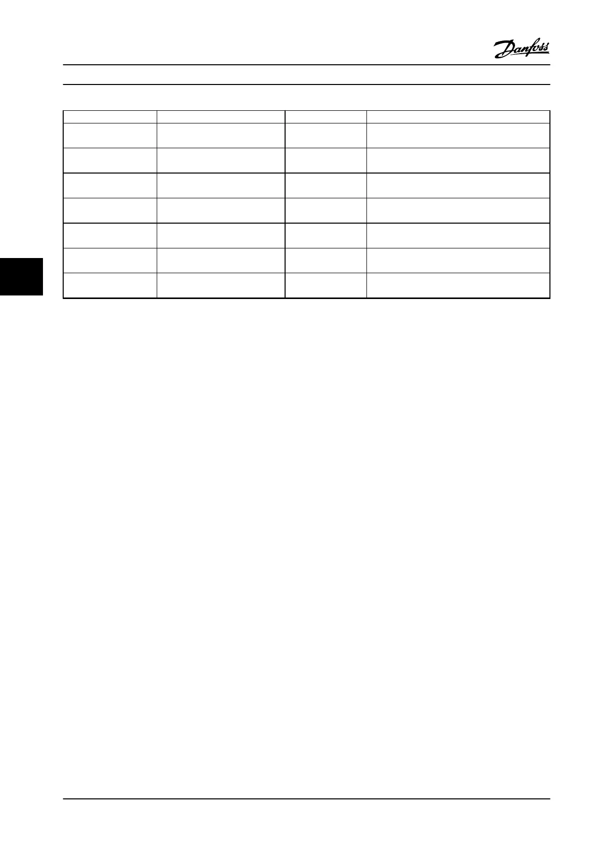
Parameter Range Default Function
5-40 Function Relay [0]
Function relay
See 5-40 Function Relay Alarm Select the function to control output relay 1.
5-40 Function Relay [1]
Function relay
See 5-40 Function Relay Drive running Select the function to control output relay 2.
6-10 Terminal 53 Low
Voltage
0–10 V 0.07 V Enter the voltage that corresponds to the low
reference value.
6-11 Terminal 53 High
Voltage
0–10 V 10 V Enter the voltage that corresponds to the high
reference value.
6-12 Terminal 53 Low
Current
0–20 mA 4 Enter the current that corresponds to the low
reference value.
6-13 Terminal 53 High
Current
0–20 mA 20 Enter the current that corresponds to the high
reference value.
6-19 Terminal 53 mode [0] Current
[1] Voltage
1 Select if terminal 53 is used for current or voltage
input.
Table 6.4 Open-loop Application
How to Program Design Guide
78 Danfoss A/S © Rev. 2014-01-14 All rights reserved. MG18C522
66

 Loading...


