DM16E1 / DM4E1 Operation and Installation Manual - 204-4001-19 100
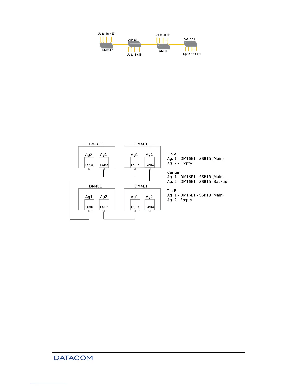
Figure 33. Example of In-Line topology
Connect power supply, tributaries, aggregates and Ethernet cable if necessary. When connecting the
aggregate interface, be careful to connect TX to RX when using two fibers and 1310 nm to 1550 nm cards
when using monofiber.
In cases of in-line topology, the information within the link flows in one main direction, which is given by the
reception of the main aggregate card. As such, in intermediate devices, the backup card TX fiber should
be connected to the main card RX fiber of the next device, and so on, until the device positioned at the end
of the link is reached. The end device can have a single card. Similarly, the main card TX fiber should be
connected to the backup card RX fiber of the previous device and so on, until the other end of the link is
reached, thus resulting in an in-line arrangement. When monofiber cards are used, the main card must be
connected to the backup card of the next device and so on. Please note that each card is connected to
only one device, so that line may be segmented into independent connections, allowing the use of 2-fiber
cards, monofiber cards and electric interfaces (e.g. for radio links).
Figure 34. Connections in In-Line topology
All devices should connect automatically if all connections are done correctly. Use the terminal connector
for configuration changes and to check the status of local or remote devices.
Refer to chapter 3 for additional information about configuration using the terminal port. SNMP
management is detailed on chapter 13.2.
15.8. Optic Modem Topology
When the equipment is configured to operate in Optic Modem, the E3 electric interface from the additional
card is used automatically. All other tributaries are automatically disabled.
Physical connections are available on tributary 1 connections. Tributary 1 locking is automatic.
Check if the additional E3 tributary card (DM16E1-E3Ei) is present. Please note that this card is optional. It
is installed internally in the same position of the internal bridge.
Devices are factory preset for point to point topology so they do not need any additional settings when only
tributaries E1 (G.703) are used. Aggregate 1 is considered the main link and Aggregate 2 is the backup
link (with automatic backup). With this initial setup, other configurations can be made remotely except for
some SNMP management settings.