DM16E1 / DM4E1 Operation and Installation Manual - 204-4001-19 16
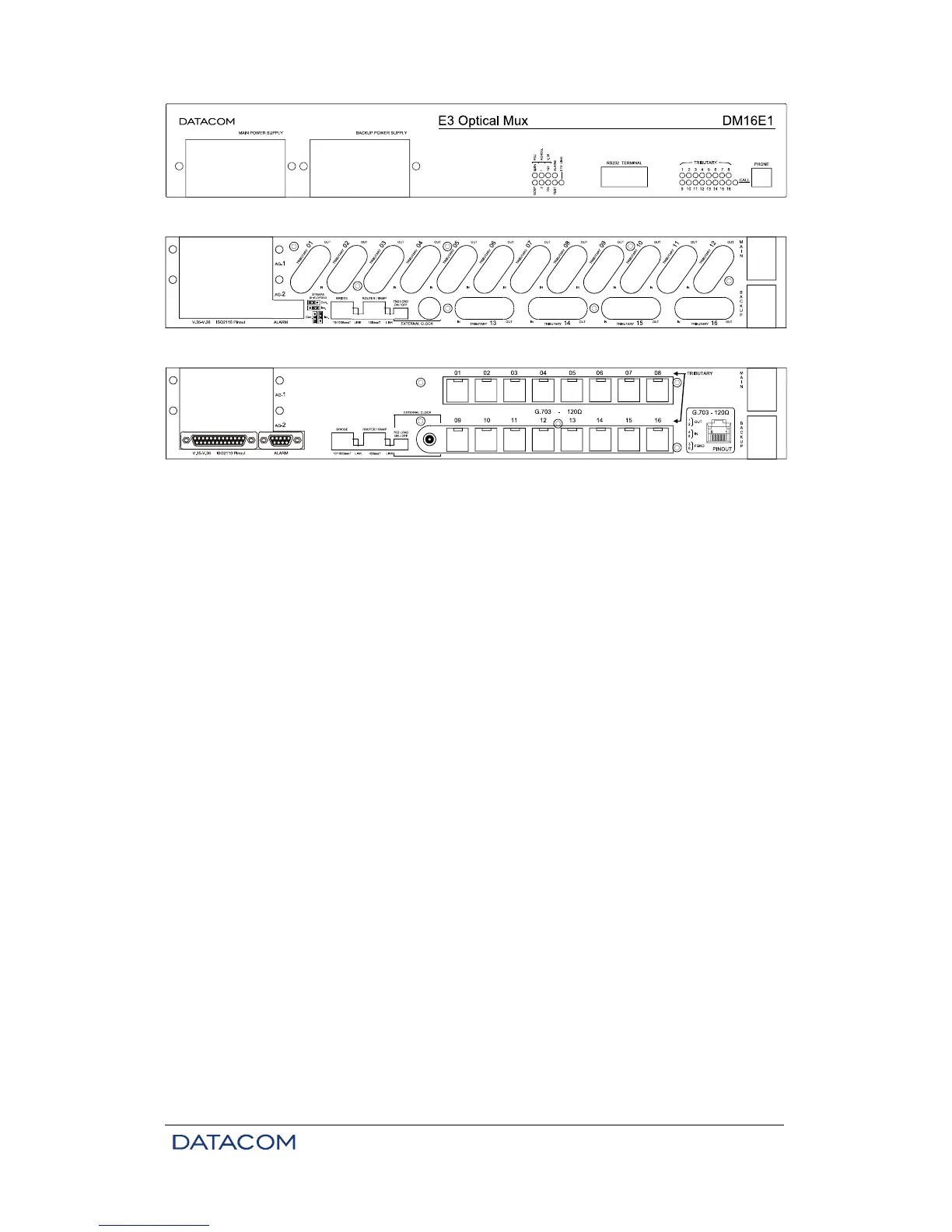
Figure 5. Front panel of the DM16E1
Figure 6. Rear panel of the DM16E1 with either IEC or BNC connectors
Figure 7. Rear panel of the DM16E1 with RJ45 connectors
2.7. Led Indicators
PSU (MAIN and BACKUP): indicate the status of the power unit supplies. When lit, it signals that the
supply is operating normally; when unlit, it shows that there is no unit; when flashing, it indicates a
defective unit, or one which is disconnected from the electric network.
AGGREG (1 and 2): indicates the status of the aggregate interface. Unlit shows that no interface is
present; continually lit shows a synchronized interface; flashing indicates LOS or AIS. More details in item
6.3.
TRIBUTARY (1 to 16 in DM16E1 and 1 to 4 in DM4E1): indicates the status of the equipment E1 G.703
tributaries. The behavior pattern is similar to that of aggregate led indicators. More details in item 4.2.
V.35 (103 and 104): reflects the status of 103 and 104 signals at the V.35 tributary.
ALARM: indicates simultaneously alarms of high and low priority. This indication will remain on until the
alarm is eliminated and the user initiates a command of recognition through the terminal port or via the
DmView SNMP management software. More details in chapter 12.
TEST: indicates that the equipment is undergoing a test. It will remain lit while any interface is executing a
test.
ETH LINK: indicates the presence of a signal at the Ethernet port on the rear panel of the equipment.
CALL: lights up when the service channel telephone is off of the hook; flashes when the equipment
receives a call from the remote equipment.
2.8. Equipment Interfaces
TERMINAL: port RS232 (V.24/V.28) in DB9 female connector, utilized to connect the equipment to the
configuration terminal by means of a serial cable. The pinout description of this connector can be seen in
chapter 15.
PHONE: connection of a fixed telephone with an RJ11 connector using a service channel. Used for
communication between operators during installation and maintenance of the link.
AGGREGATES (AG1 and AG2): two slots for the insertion of aggregate interfaces, either optic or electric.