DM16E1 / DM4E1 Operation and Installation Manual - 204-4001-19 41
Figure 11. Local digital loopback at a G.703 interface
4.9. Terminal Operation
E1 channels can be configured, monitored or tested via the VT100 terminal, without the need for any
special program.
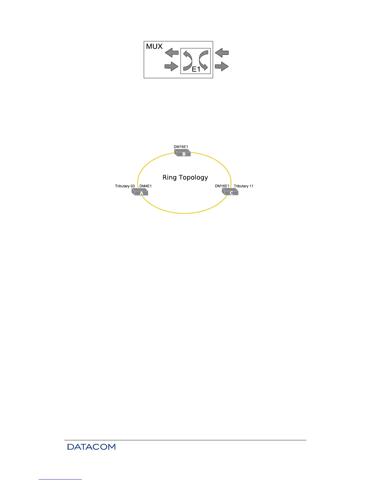
Figure 12 shows the tributary configuration that is necessary to set up an E1 channel in a mixed DM4E1 /
DM16E1 ring.
Figure 12. Example of ring topology
When in doubt regarding equipment and aggregate configuration, see chapter 3.10.1 and 6.7.
New configurations must be enabled in order to take effect, and may be saved in E2PROM. When in doubt
regarding memory or menu access, see chapter 3.
4.9.1. Configuration
Configuration of DM16E1 and DM4E1 tributaries consists of two parts: aggregate map configuration and
port specification.
If required, one or more positions can be reserved for tributaries in the aggregate map. These are
configured using a letter (or letter and number) referring to a specific application for the tributary.
Screen below shows how the tributary table should be configured for the link in the example above, using
the settings/map menu:
• Position 11 in DM16E1A to “G” (physical tributary 11)
• Position 11 in DM16E1B to “-“ (pass through)
• Position 11 in DM4E1C to “G3” (physical tributary 3)