DM16E1 / DM4E1 Operation and Installation Manual - 204-4001-19 59
7. ELECTRIC E3 INTERFACE CARDS
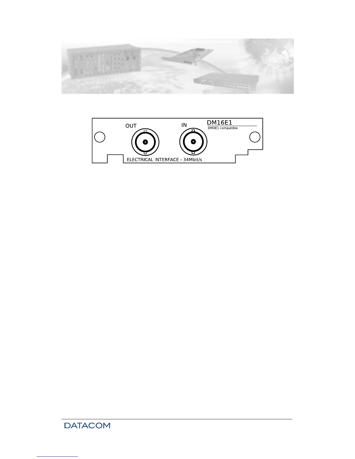
7.1. Aggregate Cards - DM16E1-E3E
Figure 21. Electric E3 interface card panel
The DM16E1-E3E card implements an electric interface with a nominal speed of 34368 kbit/s,
corresponding to an E3 channel. It can be used on both DM16E1 and DM4E1.
The interfaces use a 75-ohm coaxial cable. The connection can be made through a BNC (standard) or a
IEC169/13 (DIN47295 1.6/5.6) connector.
The external shields of the coaxial cables can be grounded via straps, see Figure 24.
These interfaces can work in two different ways. The most common way is to work as an aggregate
interface, using DM16E1 or DM4E1 as PDH multiplexers with electric output. The other way is to work as
an electric vs. optic converter. In this case, an electric card and an optic card are used, and the signals
from the electric interface are converted into optic and vice-versa.
7.2. DM16E1-E3Ei Internal Card
When it is necessary to operate as an electric x optic converter, with two optic interface cards for
protection (1 + 1), it is possible to install an electric E3 interface card in the equipment.
This card is called DM16E1-E3Ei and it cannot be used as an aggregate card. It is installed in the position
of the Ethernet Remote Bridge, and the connections are made through the tributary 1 connectors.
7.3. Status of the Electric Aggregate on the Front Panel
For each aggregate interface, there is a status led on the front panel named AGREG1 and AGREG2. The
possible status options indicated are loss of frame synchronization (optical modem topologies: ATM, Point-
to-Point, Regular Ring and Cross Ring), AIS reception (transparent optic modem), or absence of optic
signal.
There are still special signals for the Backup aggregate card, used to indicate the locking of the link in case
of failure. When receiving these signals, the Backup cards turn on the led, which also indicates that the E3
synchronization is OK. Table 12 presents the codes for each status: