DM16E1 / DM4E1 Operation and Installation Manual - 204-4001-19 65
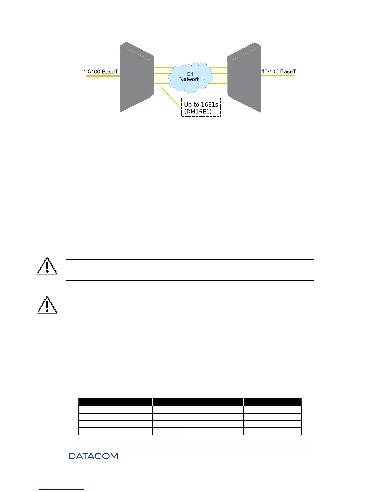
Figure 25. Example of bridge inverse multiplexing
In this configuration, the 10/100baseT Ethernet signal received from the Bridge port is decomposed into 2
Mbit/s E1 signals. These signals may be directed to the G.703 tributary (as shown in Figure 25) or to the
aggregate.
Please note how easy it is to interconnect the LAN through the E1 tributaries made available by the
exchange. When the Bridge is configured with inverse multiplexing, it is also possible to configure the
clocks of the E1 tributaries as regenerated from the E1 network.
Each E1 channel used in inverse multiplexing systems is monitored individually, being discarded whenever
presenting physical problems. The discarding and return of E1 channels is automatic, i.e., the exchange’s
interference is not necessary, and the quality of the channel is guaranteed.
E1 channels used in inverse multiplexing systems may be directed to E1 tributaries as well as aggregates.
The latter configuration allows the connection of a LAN between two points in a ring.
Due to the allocation system used in Bridge operation with inverse multiplexing, the effective bandwidth in
a single TCP connection through the interface can be lower than the configured value. It is recommended
the use of bridge card_HW2 for this type of application.
8.1. Ethernet Physical Level
According to the IEEE 802.3 specification, the Ethernet interface should be of the 10/100BaseT type
(twisted pair).
On the rear panel of the card, there is a led that indicates the status of the Ethernet link of the Bridge card.
Table 13 presents the pinout for the RJ45 connector, which is the same as that used in local PC networks.
This means that the connection to Ethernet hubs is usually made by direct cables.
Function Signal 8-pin RJ45 Signal source
Transmitted data – wire + TX+ 1 Mux
Transmitted data – wire - TX- 2 Mux