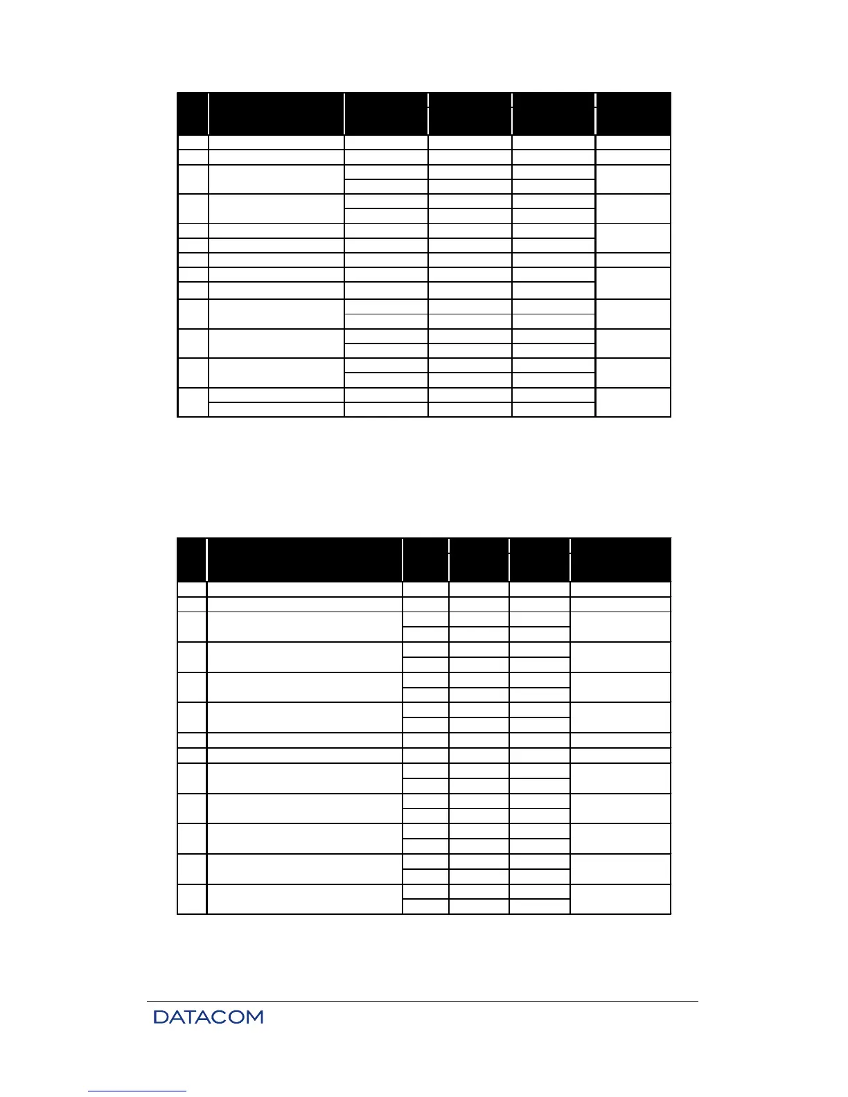
ISO2593
101 Frame ground P. Gnd 1 A
102 Signal ground S. Gnd 7 B
TDa 2 P
TDb 14 S
RDa 3 R
RDb 16 T
105 Request to send RTS 4 C
106 Ready to send CTSa 5 D
107 Modem ready DSR 6 E Mux
108 Terminal ready DTR 20 H
109 Aggregate status+ DCD 8 F
XTCa 24 U
XTCb 11 W
TCa 15 Y
TCb 12 a/AA
RCa 17 V
RCb 9 X
External reception ERCa 22*
clock ERCb 23*
CT Function Signal
Signal
source
103 Data transmitted DTE
104 Data received Mux
128 DTE
113
DTE transmission
clock
DTE
114 Transmission clock Mux
DTE
DTE
115 Reception clock Mux
Table 8. Pinout for V.35
* In ISO2110 Amd.1, pins ERCa (22) and ERCb (23) correspond to CT108 and CT102-b (DTE Common
Return), respectively.
+ At the digital interface, CT109 reflects the status of the aggregate, remaining off whenever the aggregate
is in an error condition.
DB25 DB37
ISO2110
Amd.1
ISO4902
101 Frame ground P. Gnd 1 1
102 Signal ground S. Gnd 7 19
TDa 2 4
TDb 14 22
RDa 3 6
RDb 16 24
RTSa 4 7
RTSb 19 25
CTSa 5 9
CTSb 13 27
107 Modem ready DSR 6 11 Mux
108 Terminal ready DTR 20 12 DTE
DCDa 8 13
DCDb 10 31
XTCa 24 17
XTCb 11 35
TCa 15 5
TCb 12 23
RCa 17 8
RCb 9 26
ERCa 22*
ERCb 23*
DTE
Signal source
103 Data transmitted DTE
CT Function Signal
104 Data received Mux
105 Request to send DTE
106 Ready to send Mux
109 Aggretate status+ Mux
Mux
113 DTE transmission clock DTE
114 Transmission clock Mux
External reception clock128
115 Reception clock
Table 9. Pinout for V.36/V.11
* In ISO2110 Amd.1, pins ERCa (22) and ERCb (23) correspond to CT108 and CT102-b (DTE Common
Return), respectively.