DM16E1 / DM4E1 Operation and Installation Manual - 204-4001-19 53
DM16E1-SLB15 – Optic E3 interface over 1 singlemode fiber at 1550 nm TX and 1310 nm RX, long
wavelength, nominal power: –5dBm.
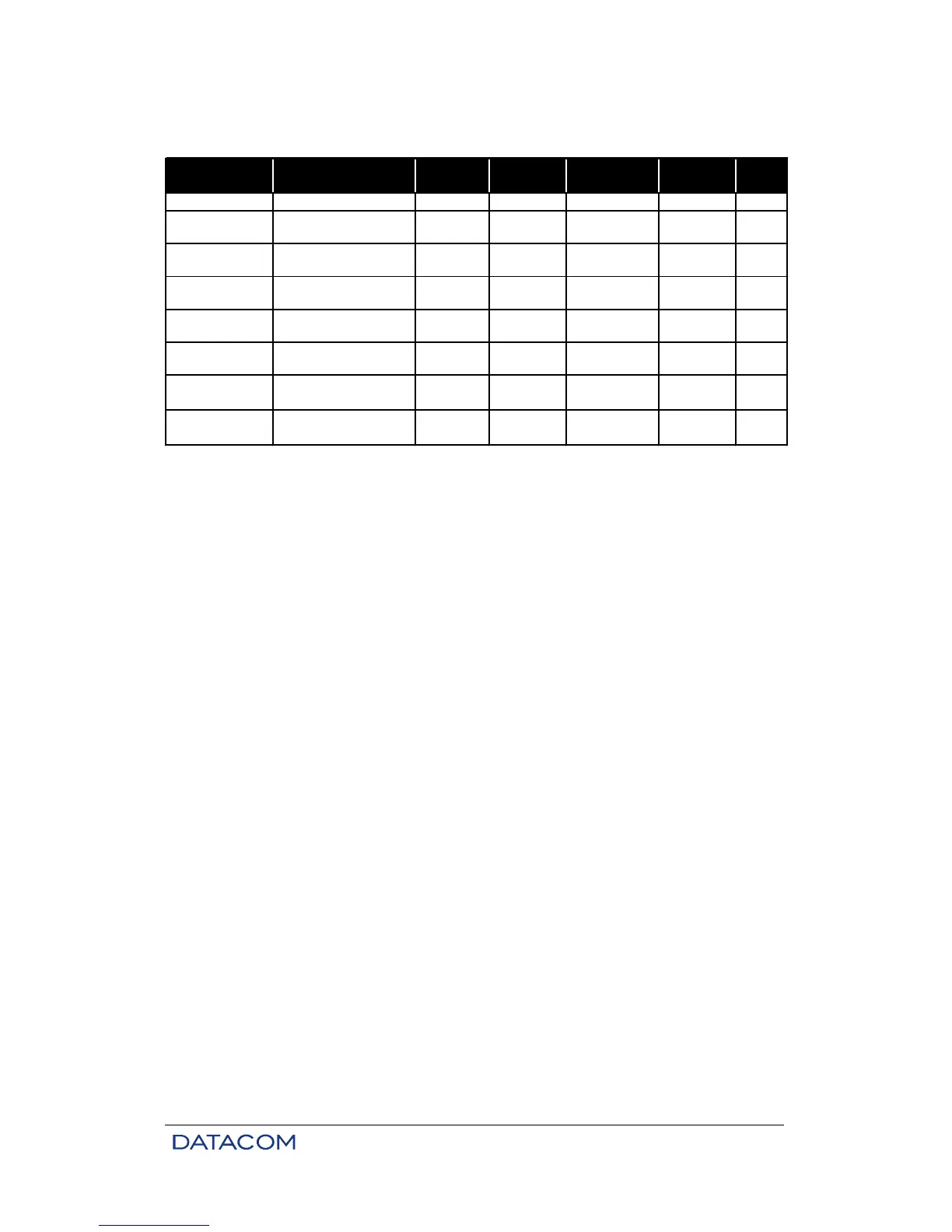
MS13 Multimode 1310 -20dBm -31dBm
~ 2km 1
SS13
Singlemode 2 fibers
short range
1310 -15dBm -34dBm ~ 45km 2
SS15
Singlemode 2 fibers
short range
1550 -15dBm -34dBm ~ 64km 3
SL13
SLB15
~ 39km-31dBm
-5dBm
P.S.Description Tx [nm]
Estimated
Range*
SensitivityModule
2
TX Minimal
Power
2
Singlemode Monofiber
short range
1310 ou
1550†
Singlemode Monofiber
long range
1310 ou
1550†
~ 72km
-15dBm
-34dBm
Table 10. Characteristics of optic interfaces
* The estimated range already foresees 3db loss, caused by connections, splices and other optic
phenomenon.
† 1310nm transmission and 1550nm reception or vice-versa
.
The 1310nm attenuation is preponderant.
1) Considering Multimode Fiber with 2dB/km loss (1310nm).
2) Considering Singlemode Fiber with 0,36dB/km loss (1310nm).
3) Considering Singlemode Fiber with 0,25dB/km loss (1550nm).
6.2. Characteristics of Optic E3 Interfaces
Transmitter: 1310 or 1550 nm diode laser, power options for short or long wavelength.
Multi mode receiver: PIN photodiode. Minimal level: –31 dBm for BER (Bit Error Rate) of 10-12; maximal
signal intensity: –14 dBm.
Single mode receiver: PIN photodiode. Minimal level: –34 dBm for BER of 10-12; maximal signal intensity:
–8 dBm.
The use of an attenuator to adjust power and avoid saturation of the preamplifier may be required for very
short links in which receiver power is greater than the power specified above.
Wavelength may vary due to link quality or environmental conditions (grounding, EMI). The equipment is
set at factory with the minimum power specified. However, it is usually several dB above the minimal
specification (e.g., -10 dBm in a short-wavelength card).
Transmitters have a circuit that compensates for laser variations caused by temperature and aging.
Optic signal encoding technology is proprietary and guarantees BER levels for any kind of data
transmitted.
6.3. Optic Interface Status Indicators on the Front Panel
There is a status led on the front panel for each aggregate interface – AGREG1 and AGREG2. The status
leds indicate frame synchronization loss, AIS reception (transparent optic modem), or absence of optic
signal.