DM16E1 / DM4E1 Operation and Installation Manual - 204-4001-19 101
If a completely transparent E3 tributary is needed, it can also be configured remotely. Once this is done,
there will be no access to the remote equipment via in band management. Future changes must be done
via local management or via SNMP (Ethernet) management. The service channel is not enabled under this
configuration. It is important to configure the local modem similarly to the remote one.
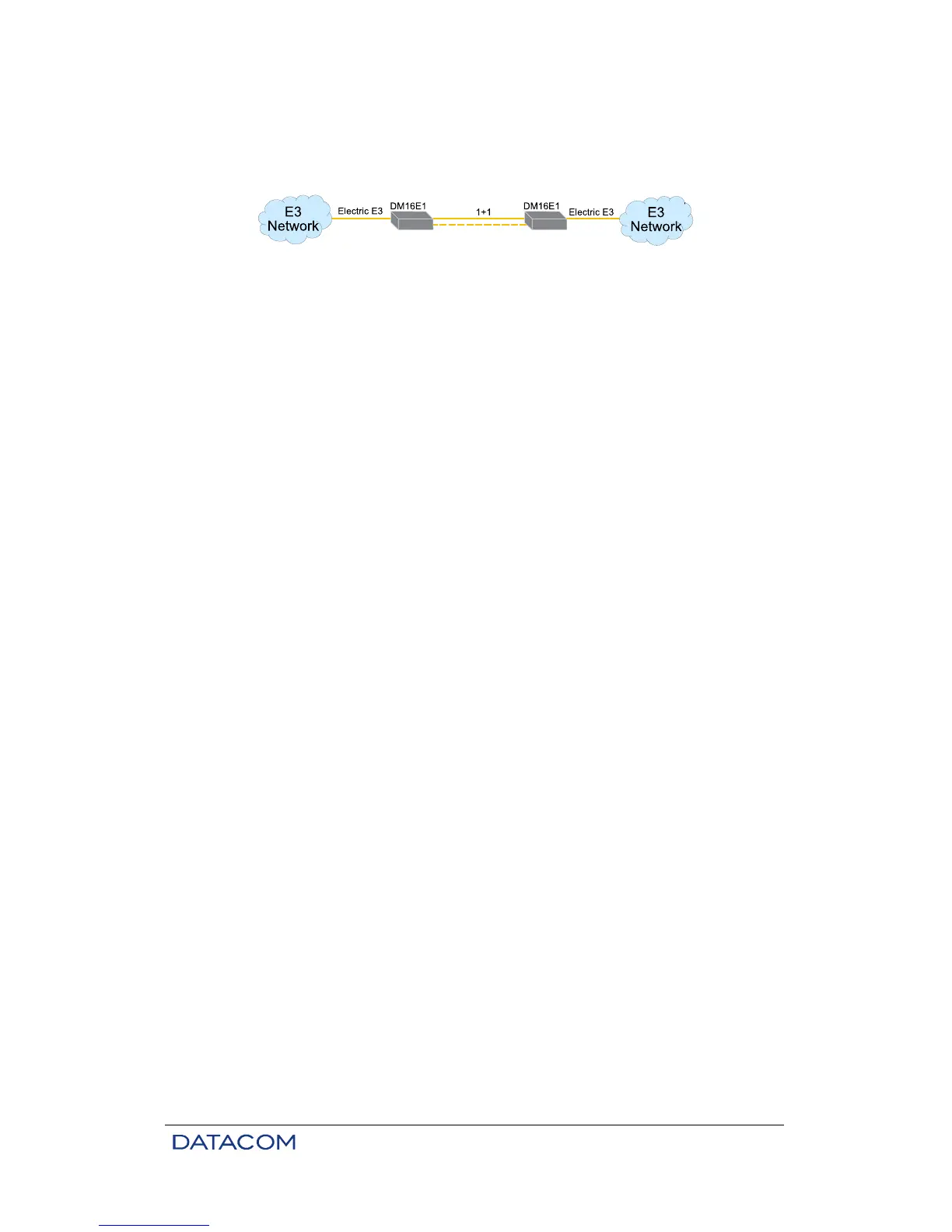
Figure 35. Example of Optic Modem topology
The following topologies are possible with optic modems:
Transparent optic modem - The IN of the E3 tributary is routed to the OUT of the aggregate and the IN of
the aggregate is routed to the OUT of the E3 Tributary. No modification is made on the frame structures.
This arrangement may be considered as an interface converter with backup facilities.
ATM Optic Modem - It works like Transparent Optic Modem, but it is used to carry ATM over E3. In this
topology, the device must only be connected to other device with ATM Optic Modem topology configured
(FLOS Alarm indication in the aggregate when connected to any other topology). FLOS Alarm indication in
the E3 tributary, if the E3 signal doesn’t have ATM cells according to G.832
Point to point optic modem - The IN of the E3 tributary is routed to the OUT of the aggregate and the IN of
the aggregate is routed to the OUT of the E3 Tributary. The E3 Frame is modified for insertion of the
remote (in band) management. Thus the devices connected to the tributary must operate with E2/E3
structures.
Optic modem with regular ring - The IN of the E3 tributary is routed to the OUT of the aggregate and the IN
of the aggregate is routed to the OUT of the E3 Tributary. The E3 Frame is modified for insertion of the
remote (in band) management. Thus the devices connected to the tributary must operate with E3
structures. They also must have the pass-through (drop-insert) facility. The device connected to the E3
tributary is inserted in a ring with regular-ring topology, being able to share 2M channels with other devices
contained in the ring. Management will be able to remotely configure the device that is directly connected
to the ring. The device connected to the E3 tributary must be configured directly. This configuration is
suitable to three or more devices. It should not be used in a two devices setup.
Optic modem with cross ring - The IN of the E3 tributary is routed to the OUT of the aggregate and the IN
of the aggregate is routed to the OUT of the E3 Tributary. The E3 Frame is modified for insertion of the
remote (in band) management. Thus the devices connected to the tributary must operate with E3
structures. They also must have the pass-through (drop-insert) facility. The device connected to the E3
tributary is inserted in a ring with cross-ring topology, being able to share 2M channels with other devices
contained in the ring. Management will be able to remotely configure the device that is directly connected
to the ring. The device connected to the E3 tributary must be configured directly.
Connect power supply, tributaries, aggregates and Ethernet cable if necessary. When connecting the
aggregate, be careful to connect TX to RX when using two fibers and 1310 nm to 1550 nm cards when
using monofiber.
All devices should connect automatically if all connections are done correctly. Use the terminal connector
for configuration changes and to check the status of local or remote devices.
Refer to chapter 3 for additional information about configuration using the terminal port. SNMP
management is detailed on chapter 13.2.
15.9. Interface Converter Topology
This topology does not have remote management (in band), so each device must be locally configured.
Only the aggregate interfaces are disabled. All tributaries are automatically disabled.
Connect power supply, tributaries, aggregates and Ethernet cable if necessary. When connecting the
aggregate, be careful to connect TX to RX when using two fibers and 1310 nm to 1550 nm cards when
using monofiber.