DM16E1 / DM4E1 Operation and Installation Manual - 204-4001-19 60
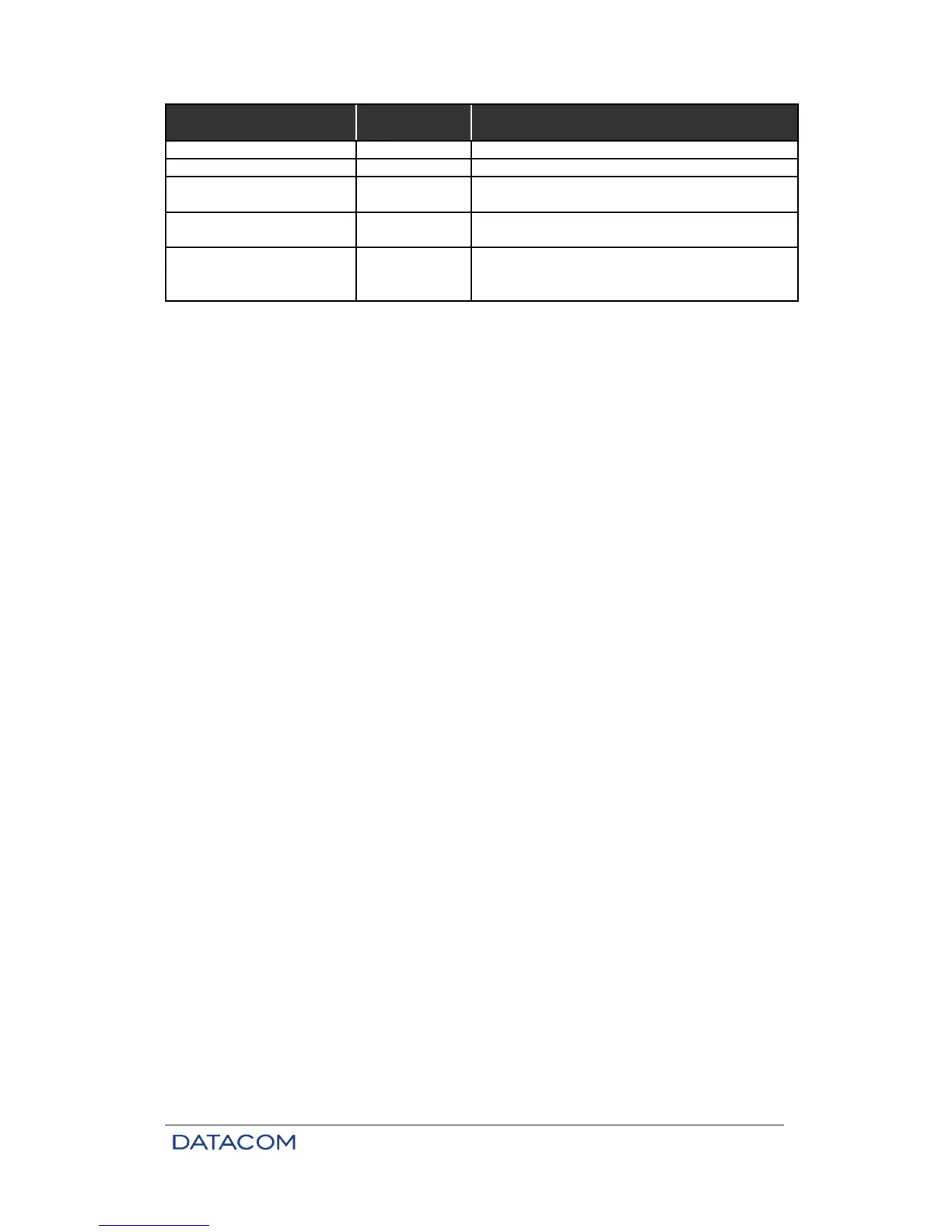
Indication AG1 or AG2 led Comments
Absent / Inactivated Card Off Indicates insertion of an incompatible card
LOS (Loss of RX signal) Quick flashing Led flashes once and is off for about 1s
Loss of Synchronization
(1)
Slow flashing Led flashes slowly, alternating on/off every 0.5 s
AIS Quick flashing
Led flashes fast and continuously, about 10 times
Table 12. Leds indications for electric aggregates (front panel)
1) In the case of Backup cards, it indicates that the link has problems.
2) It also indicates that the link is OK for Backup cards.
7.4. Status Indicators of the Internal E3 Card
The synchronization status of the internal electric E3 cards or aggregate cards can be visualized through
the Terminal port or through the DmView software.
When executing tests on this card, the TEST led on the front panel turns on.
7.5. Electric Characteristics of E3 G.703 Interface
Speed: 34368 kbit/s ± 20 PPM
Pulse format: rectangular
Number of pairs in each transmission direction: 1 coaxial pair
Nominal impedance: 75 ohms resistive
Peak voltage of a pulse: 1 V ± 0.1 V
Peak voltage of a space: 0 V ± 0.1 V
Nominal length of a pulse: 14.55 nanoseconds
Relation between amplitude of positive and negative pulses at midpoint of pulse width: from 0.95 to 1.05
Relation between width of positive and negative pulses at half nominal amplitude: from 0.95 to 1.05.
7.6. Electric E3 Interface Configurations
The following configurations are possible:
• Alarm generation enabling by the interface.
• Test execution enabling by the interface.
7.7. Local Analog Loopback – LAL
The local analog loopback is used to test the analog part of the interface card circuits. The figure below
gives an example of test conditions.