MATRIX 300™ REFERENCE MANUAL
A ALTERNATIVE CONNECTIONS
The connector pinouts and notes given in this appendix are for custom cabling applications.
POWER, COM AND I/O CONNECTOR
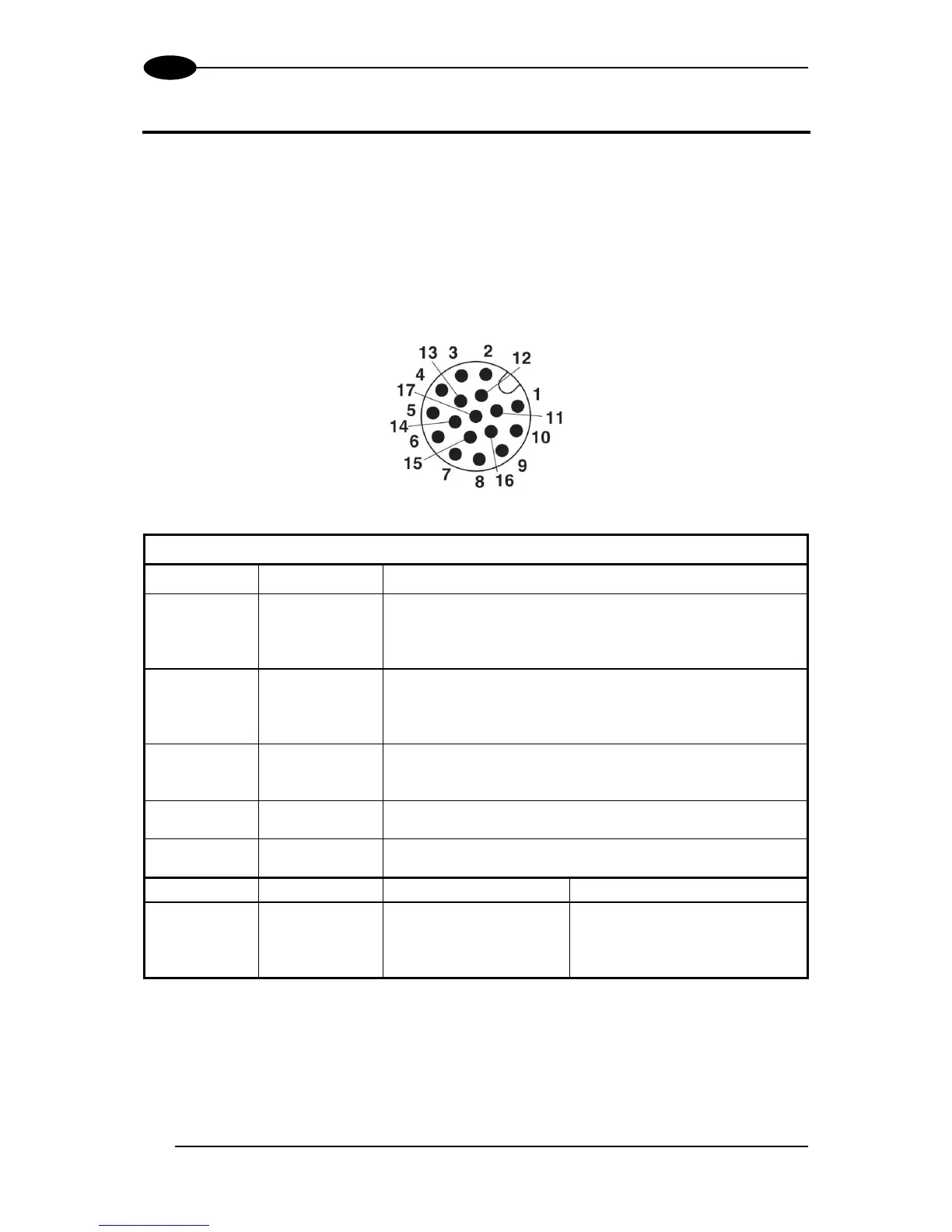
The Matrix 300™ reader is equipped with an M12 17-pin male connector for connection to
the power supply, serial interfaces and input/output signals. The details of the connector pins
are indicated in the following table:
Figure 88 – M12 17-pin male COM, I/O and Power Connector
Power, COM and I/O Connector Pinout
Power supply input voltage +
Power supply input voltage -
Connector case provides electrical connection to the
chassis
External Trigger A (polarity insensitive)
External Trigger B (polarity insensitive)
Input 2 A (polarity insensitive)
Input 2 B (polarity insensitive)
(NPN or PNP short circuit protected
and software programmable)
MAIN
INTERFACE
(SW
SELECTABLE)
* Do not leave floating, see par. 4.2.2 for connection details.
In order to meet EMC requirements:
connect the reader chassis to the plant earth ground by means of a flat copper braid
shorter than 100 mm;
connect your cable shield to the locking ring nut of the connector.