5.2 ID-NET™ SYNCHRONIZED NETWORK
The ID-NET™ connection is used to collect data from several readers to build a multi-point or
a multi-sided reading system; there can be one master and up to 31 slaves connected
together.
The slave readers are connected together using the ID-NET™ interface. Every slave reader
must have an ID-NET™ address in the range 1-31.
The master reader is also connected to the Host on the RS232/RS485/422 main serial
interface.
For a Master/Slave Synchronized layout the External Trigger signal is unique to the system;
there is a single reading phase and a single message from the master reader to the Host
computer. It is not necessary to bring the External Trigger signal to all the readers.
In the Master/Slave Synchronized layout the Master operating mode can only be set to
Phase Mode.
The main, auxiliary, and ID-NET™ interfaces are connected as shown in the following
figures.
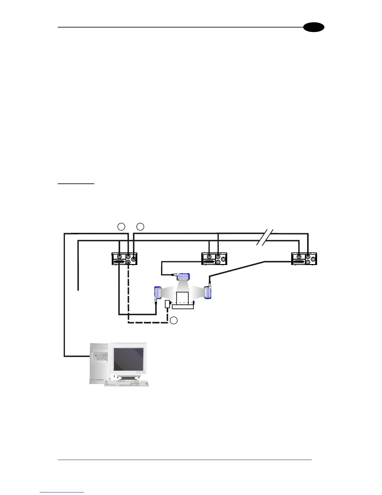
Figure 62 – ID-NET™ M/S Synchronized Layout
The Master reader can be connected to the CBX series connection box with the advantage
of the Backup and Restore configuration function (CBX + BM100 module).
Main Serial Interface (RS232 or RS485/422 Full-Duplex)
External Trigger
ID-NET™ (up to 16 devices - practical limit)