MATRIX 300™ REFERENCE MANUAL
OUTPUTS
Three general purpose non opto-isolated but short circuit protected outputs are available on
the M12 17-pin connector. See par. 4.6 for more details.
The pinout is the following:
Configurable digital output 1
Configurable digital output 2
Configurable digital output 3
The electrical features of the three outputs are the following:
Reverse-Polarity and Short-Circuit Protected
V
OUT
(I
LOAD
= 0 mA) max = 30 Vdc
V
OUT
(I
LOAD
= 100 mA) max = 3 Vdc
I
LOAD
max = 100 mA
The output signals are fully programmable being determined by the configured
Activation/Deactivation events, Deactivation Timeout or a combination of the two. Refer to
the Digital I/O folder in the VisiSet™ Help On Line for further details.
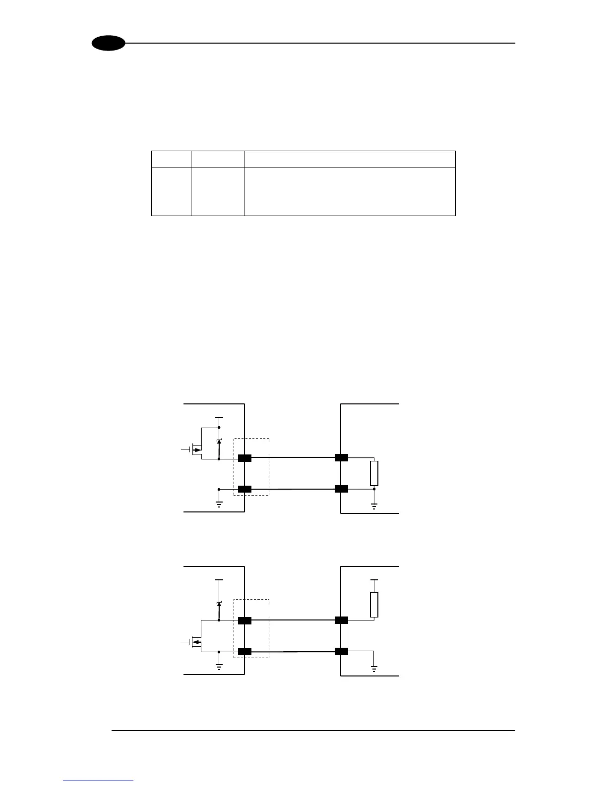
Figure 95 - PNP Output Connection
Figure 96 - NPN Output Connection