vPad-A1 OPERATORS MANUAL
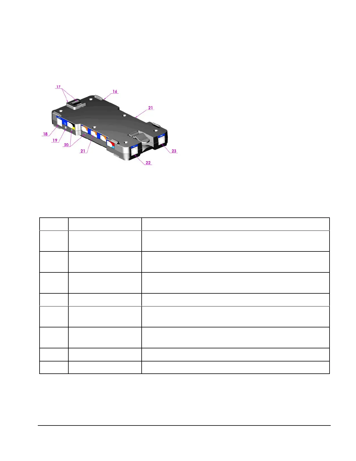
Figure 3
The vPad-PS (Patient Simulator) module
snaps in below the Base module,
connecting to power and data
communication lines through contacts on
the bottom of the Base.
Item Name Description
16 IBP Connection 2 channel IBP connectors, USB Type A, proprietary wiring (right
side)
17 Power/Data Connector 6 pin inter-module connector for power and serial
communications
18 Fetal Heart/Cardiac
Output
Output to drive Mechanical Fetal Heart and Cardiac Output,
miniDIN8 (fetal heart and CO interface boxes are optional )
19 High Level ECG Amplified ECG signal, phone jack
20 Injectate Adjust Access to coarse and fine adjustments for special cardiac output
injectate temperature value
21 ECG Snap Snap connections (10 total) for ECG monitor leads
(left and right side)
22 ECG Output extension miniDIN10 extension connection for 3 and 4 mm banana jacks
23 Temperature Connector YSI400 and YSI700 output resistance connector, miniDIN6
Setup/Chapter 3 # Page 21
 Loading...