7.2.43.7 Sub-Register 0x2A:0C – TC_PGTEST
Transmitter Calibration –Pulse Generator Test
Register file: 0x2A – Transmitter Calibration block, sub-register 0x0C is an 8-bit configuration register for use
in setting the transmitter into continuous wave (CW) mode. This CW mode is employed during the crystal
trimming operation which may be done at module manufacturing stage as part of calibrating the crystal
oscillator’s operating frequency. At all other times, for normal operation, the value in this register should be
left in its default power on value of 0x00.
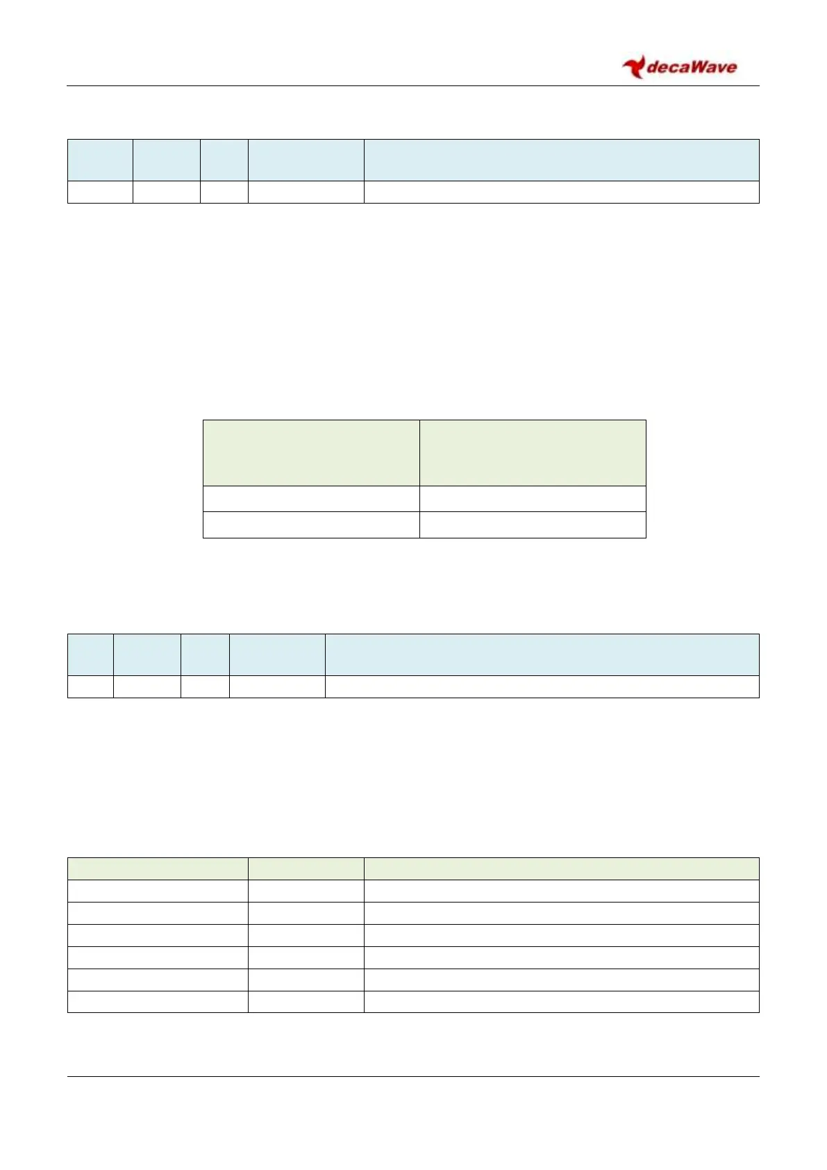
Table 41:
Sub-Register 0x2A:0C – TC_PGTEST values
8-bit value to program to
Sub-Register 0x2A:0C – TC_PGTEST
Continuous Wave (CW) Test Mode
For more details of crystal trimming please refer to section 8.1 – IC Calibration – Crystal Oscillator Trim.
7.2.44 Register file: 0x2B – Frequency synthesiser control block
Frequency synthesiser control block
Register map register file 0x2B is the frequency synthesiser control block. Its main functionality is the
generation of the carrier frequency necessary for the operating channel. It contains a number of sub-
registers. An overview of these is given by Table 42. Each of these sub-registers is separately described in
the sub-sections below.
Table 42: Register file: 0x2B – Frequency synthesiser control block overview
Frequency synthesiser – Reserved area 1
Frequency synthesiser – PLL configuration
Frequency synthesiser – PLL Tuning
Frequency synthesiser – Reserved area 2
Frequency synthesiser – Crystal trim
Frequency synthesiser – Reserved area 3