7.2.46.1 Sub-Register 0x2D:00 – OTP_WDAT
Register file: 0x2D – OTP Memory Interface, sub-register 0x00 is a 32-bit register. The data value to be
programmed into an OTP location should be written here before invoking the programming function.
Writing to OTP memory is an involved procedure. For details of this please refer to section 6.3.2 –
Programming a value into OTP memory.
7.2.46.2 Sub-Register 0x2D:04 – OTP_ADDR
Register file: 0x2D – OTP Memory Interface, sub-register 0x04 is a 16-bit register used to select the address
within the OTP memory block that is being accessed (for read or write) this OTP memory interface. The
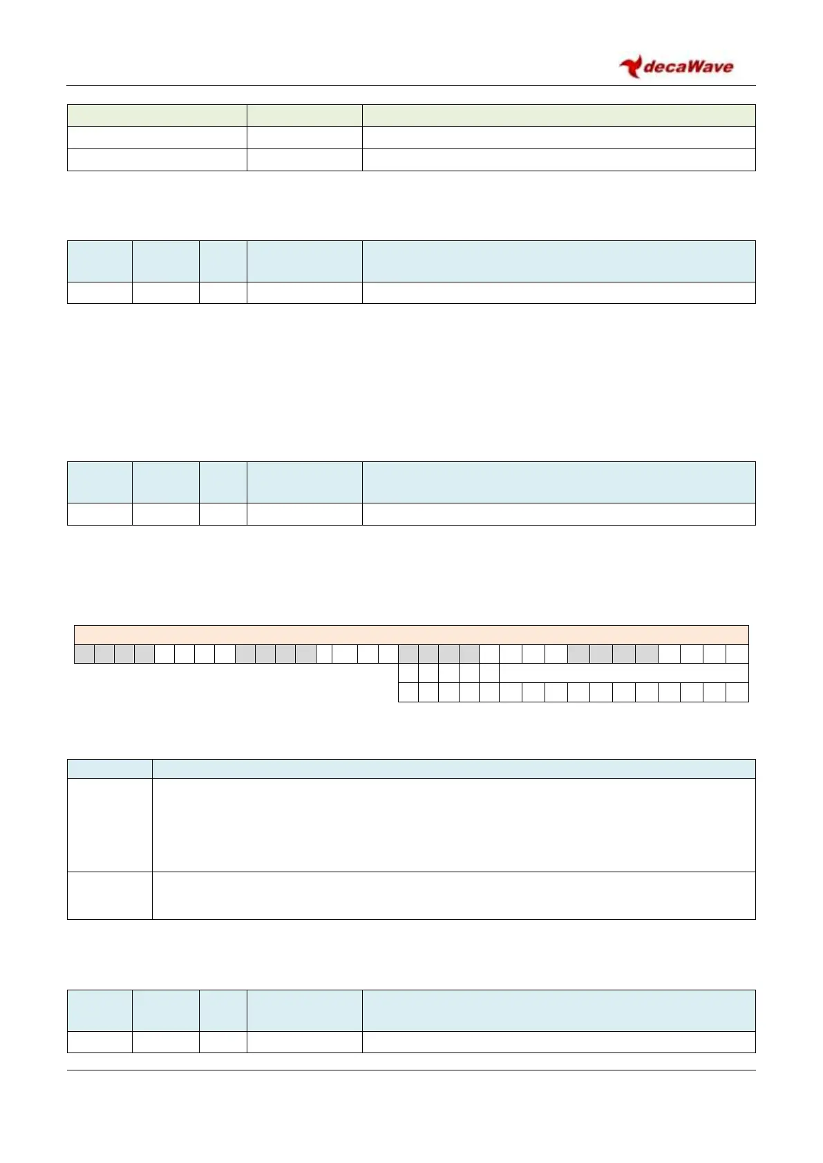
OTP_ADDR register contains the following fields:
REG:2D:04 – OTP_ADDR – OTP Address
The fields of the OTP_ADDR register are described below:
Description of fields within Sub-Register 0x2D:04 – OTP_ADDR
OTPADDR
reg:2D:04
bits:10 –0
This 11-bit field specifies the address within OTP memory that will be accessed read or written.
For details of the OTP memory map and the procedures to read and write OTP memory, please
refer to section 6.3 – Using the on-chip OTP memory.
Reserved. The remainder of this register is reserved.
7.2.46.3 Sub-Register 0x2D:06 – OTP_CTRL