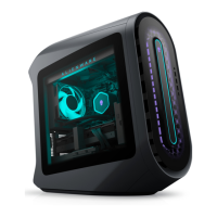
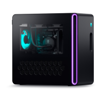
Replacing the left AlienFX side-panel connector
NOTE: Before working inside your computer, read the safety information that shipped with your computer and follow the steps
in Before working inside your computer. After working inside your computer, follow the instructions in After working inside your
computer. For more safety best practices, see the Regulatory Compliance home page at www.dell.com/regulatory_compliance.
Topics:
• Procedure
• Post-requisites
Procedure
1. Route the cable through the slot on the bracket and align the screw holes on the left AlienFX side-panel connector with the screw
holes on the bracket.
2. Replace the two screws (#6-32x6) that secure the AlienFX side-panel connector to the bracket.
3. Align the screw hole on the left AlienFX side-panel connector with the screw hole on the chassis.
4. Replace the screw (#6-32x6) that secures the left AlienFX side-panel connector to the chassis.
5. Connect the cable that connects the left AlienFX side-panel connector to the system board. See “
I/O-board components”.
Post-requisites
1. Replace the left and right side-panels. See “
Replacing the side panels”.
2. Replace the stability foot.
40
 Loading...