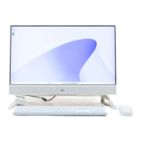
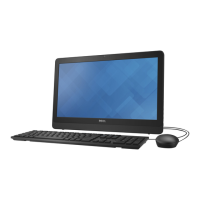
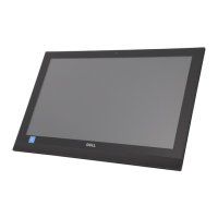
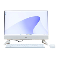
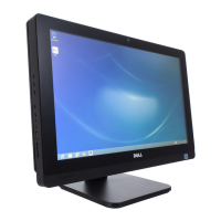
5 In sequential order indicated on the image, replace the 11 screws (M3x5) that secure the display panel to the display-assembly base.
NOTE: The screws that secure the middle frame and display-assembly base to the display panel are silver in color and
etched with "LCD" around the screw holes.
6 Remove the jig screw from the display panel.
Replacing the display panel
85

 Loading...
