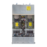
Figure 105. Cable routing−sensor board and control panel
Table 41. Cable routing for sensor board and control panel for 3.5-inch hard drive system
Item Cable From (power
distribution board)
To (sensor board and control
panels)
Sensor board
cable
Sensor board power
connector (J1)
Sensor board
Front panel
cable
Front panel
connector (J16)
Front panel 2
Front panel
cable
Front panel
connector (J18)
Front panel 1
Removing the sensor board for 2.5-inch hard drive system
Prerequisites
CAUTION: Many repairs may only be done by a certified service technician. You should only
perform troubleshooting and simple repairs as authorized in your product documentation, or as
directed by the online or telephone service and support team. Damage due to servicing that is
not authorized by Dell is not covered by your warranty. Read and follow the safety instructions
that are shipped with your product.
NOTE: Observe the routing of the cable on the chassis as you remove them from the system. You
must route these cables properly when you replace them to prevent the cables from being pinched
or crimped.
1. Follow the safety guidelines listed in the Safety instructions section.
158