4.3.2.3. IOLITE-R8: Boxed Chassis: Connectors
The IOLITE-R8 chassis also enables dual EtherCAT bus. There are two 8-pin LEMO 1B connectors on the
back panel of IOLITE-R8 used for data transfer and synchronisation on the primary bus (BUS 1) for
buffered data. The OUT connector on BUS 1 also enables power supply for external Dewesoft EtherCAT
devices.
Secondary bus (BUS 2) for unbuffered data has two RJ45 connectors (IN and OUT) for data transfer and
synchronization to 3rd party control master.
Two 2-pin LEMO 1B connectors are used for redundant power supply (PWR IN).
Above the PWR IN connector is a GND socket for grounding the IOLITE-R8.
Synchronization with Dewesoft USB data acquisition devices or connection to clock master is on
IOLITE-R8 enabled by connecting a synchronization cable to two SYNC inputs (4-pin LEMO 00).
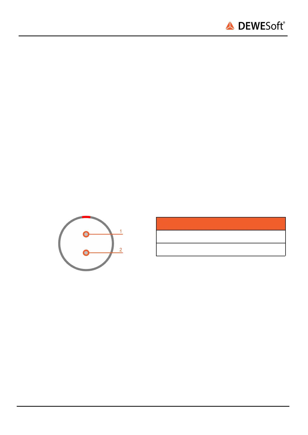
4.3.2.3.1. IOLITE-R8: Boxed Chassis: Power in: Pinout
For the power supply an unregulated DC voltage
between 12 and 48 Volts is required, which is
connected to the LEMO 1B connector on the rear
side of the chassis.
PWR IN connector (on the device): EXJ.1B.302.HLD
Mating connector (for the cable): FGG.1B.302.CLAD52Z