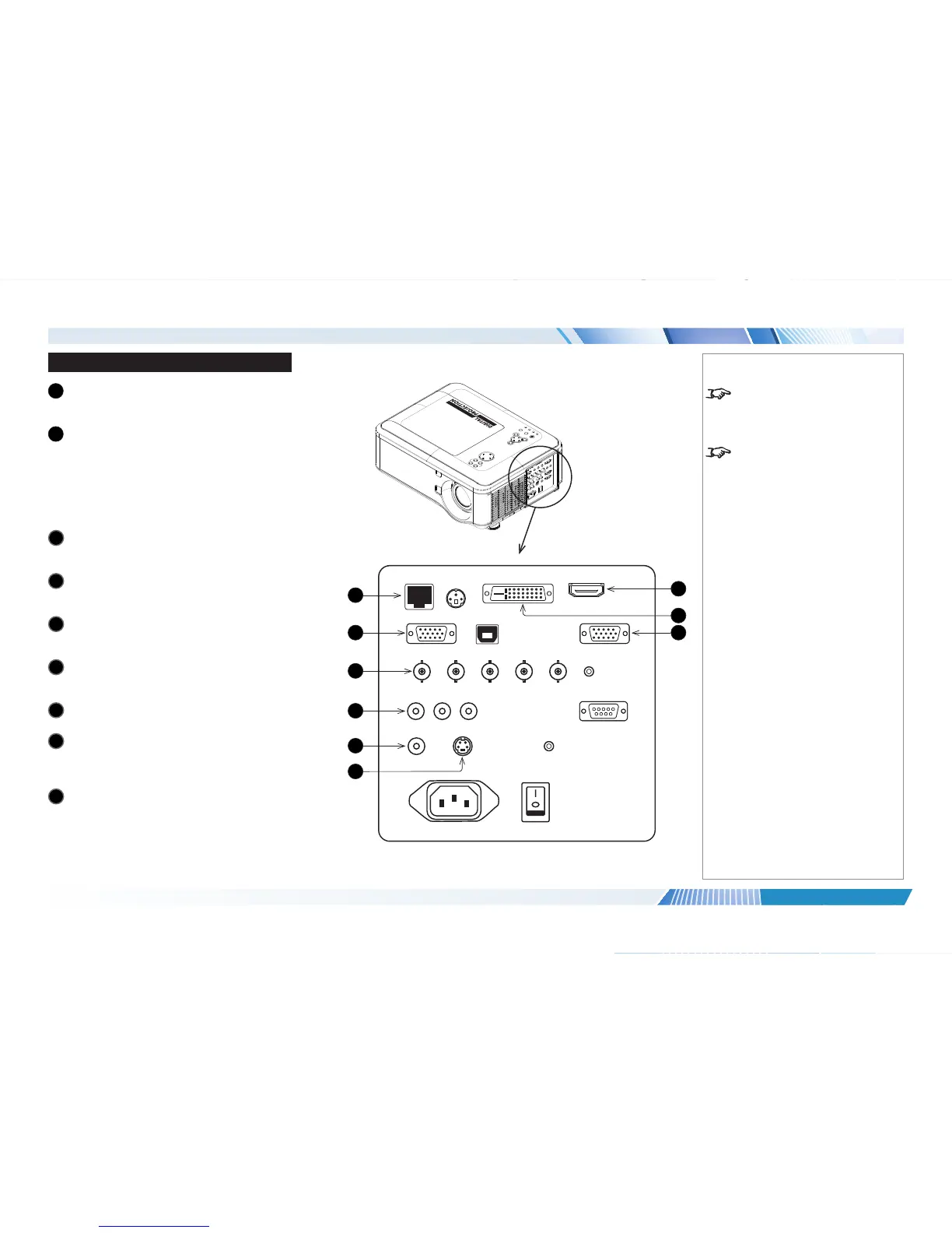
Signal Inputs And Outputs
1
HDBaseT/LAN
Receives digital signal from HDBaseT-compliant
devices.
2
VGA
This input receives analog signals from a computer.
When using this input, it is best to use a fully wired
VGA cable to connect the source to the projector.
This will allow the source to determine the projector’s
capabilities via DDC and show an optimized image.
Such cables can be identied as they have a blue
connector shell.
3
Component 1
Connect a set of RGsB, RGBHV or YCbCr cables to
the BNC connectors.
4
Component 2
Connect a set of YPbPr or YCbCr cables to the RCA
phono connectors.
5
Video
Connect a composite video cable to the single RCA
phono connector.
6
S-Video
Connect an S-Video cable to the 4-pin mini-DIN
connector.
7
HDMI
This HDMI 1.4 input supports HDCP 1.1 and DVI 1.0.
8
DVI-D
This input can receive digital (DVI-D) signal from a
compatible source.
Supports HDCP.
9
Monitor Out
Connect an analog monitor cable (VGA) to the 15-pin
D-type connector.
Notes
For a complete listing of pin
congurationsforallsignaland
control connectors, see Wiring
Details later in this Guide.
When Standby Mode is set to Eco:
the
Monitor Out connection is
disabled.
LENS SHIFT
ZOOM
–
FOCUS
+
MENU
ENTER
RETURN
SOURCE
POWER
WARNING
LAMP1
LAMP2
AUTO
7
2
1
5
3
4
9
6
8
 Loading...