ICS-90 Ion Chromatography System
2-12 Doc. 031851-05 12/04
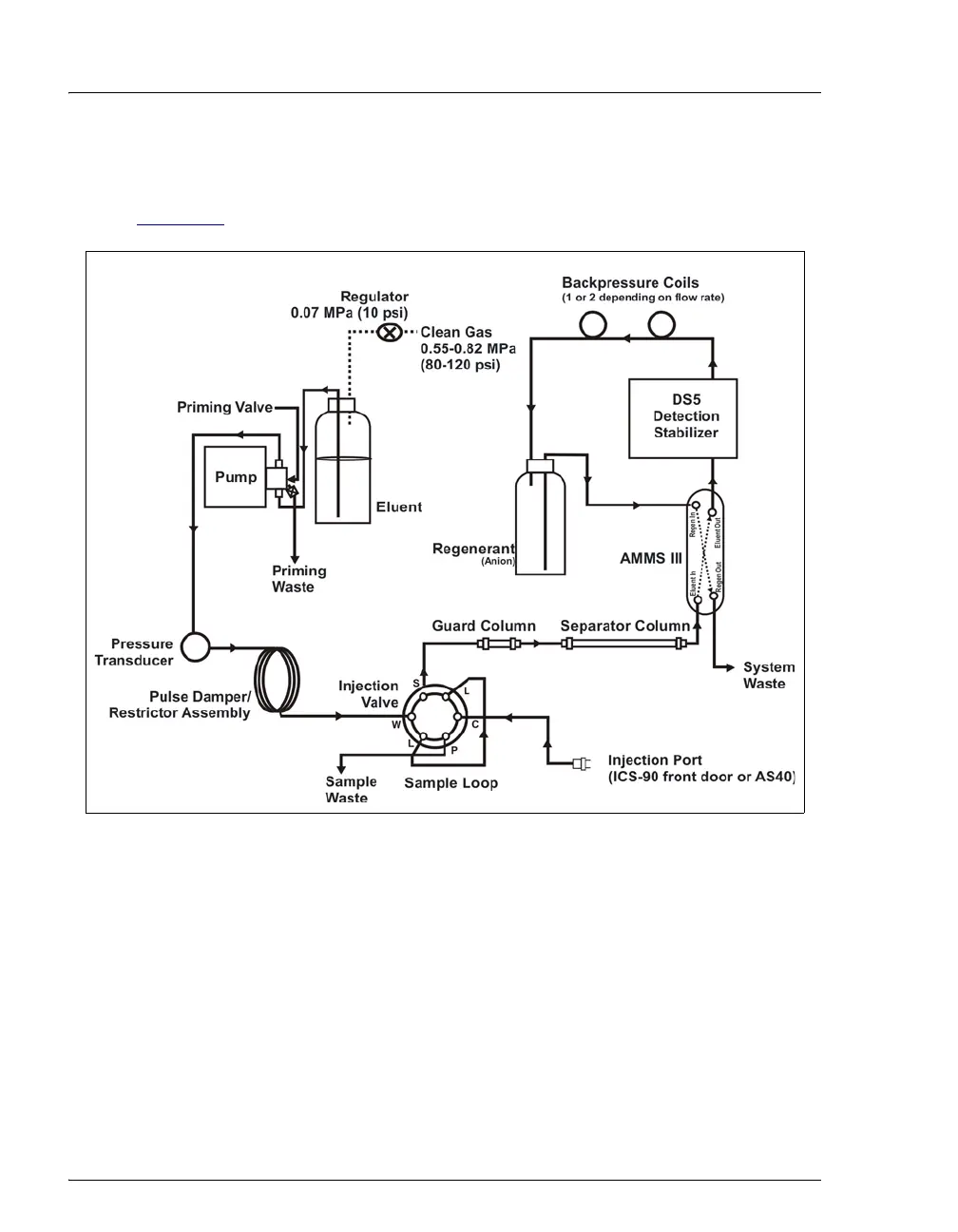
2.2 Fluid Schematic
Figure 2-7 shows the flow path through the ICS-90 Ion Chromatography System.
Liquid flows through the ICS-90 along the following flow path:
• Eluent from the eluent reservoir is pressurized by the gas, forced into the
pump, and passes through the pressure transducer. From there, it is pushed
through a pulse damper/restrictor assembly, which smooths minor pressure
variations from the high-speed pump to minimize baseline noise. The eluent
then flows into the injection valve.
• When sample is loaded into the sample loop, the injection valve toggles to the
Inject position. This combines the injected sample with the eluent and pushes
it through the sample loop.
Figure 2-7. ICS-90 Flow Schematic