B • Installation
Doc. 031851-05 12/04 B-33
B.17 Connecting the AS40 Automated Sampler (Optional)
1. Open the front door of the ICS-90 and thread the outlet line from the AS40
through the side slot near the lower ICS-90 door hinge (see Figure B-20
).
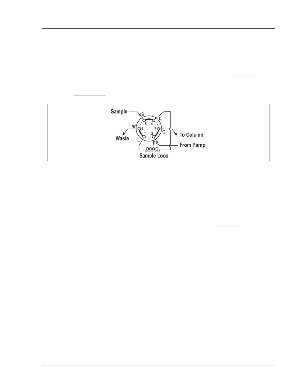
2. Connect the outlet line from the AS40 to port S (5) of the injection valve (see
Figure B-24
).
3. Follow the steps below to connect the
TTL Output connector on the ICS-90
rear panel to the
RELAY CONTROL connector on the AS40 rear panel.
a. Locate the Relay Control cable (P/N 047946) supplied with the AS40.
b. Connect the Relay Control cable's 10-pin connector to the
RELAY
CONTROL
connector on the AS40 rear panel (see Figure B-25).
Figure B-24. Injection Valve Connections