ICS-90 Ion Chromatography System
B-24 Doc. 031851-05 12/04
3. Plumb the MMS III suppressor as follows:
a. Install the suppressor onto the brackets located below the DS5 (see
Figures B-19
and B-20).
b. Remove the union
connecting ELUENT IN and ELUENT OUT and connect
ELUENT IN
and ELUENT OUT to the corresponding ports on the suppressor.
c. Remove the union connecting
REGEN IN and REGEN OUT and connect
REGEN IN and REGEN OUT to the corresponding ports on the suppressor.
4. To ensure the correct operating pressure for the suppressor, either one or two
backpressure coil(s) (P/N 045877) must be installed between the cell outlet
and the regenerant reservoir inlet. The number of coils required depends upon
the application flow rate:
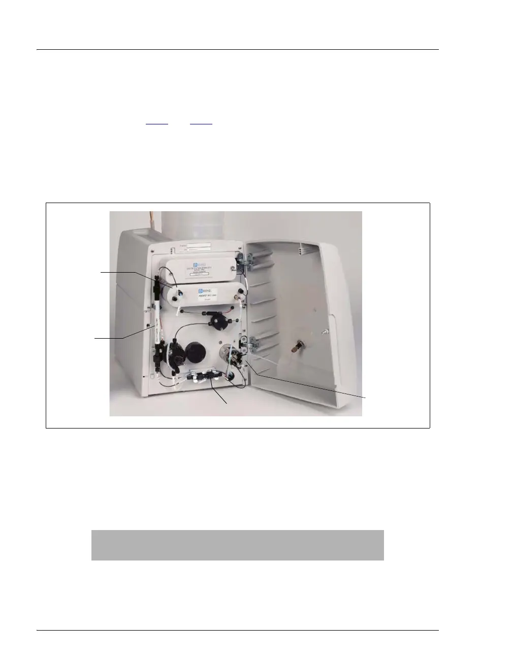
Figure B-20. ICS-90 with Columns and Suppressor Installed
Application Flow Rate Number of Required Backpressure
Coils
Less than 2 mL/min 2
2 mL/min or more 1
Separator
Column
MMS III
Suppressor
Guard Column
Side slot for
autosampler
line