B • Installation
Doc. 031851-05 12/04 B-23
a. Remove the union connecting GUARD IN and GUARD OUT and connect
GUARD IN to the guard column inlet. Check the arrow on the column
label; it should point away from the injection valve.
b. Connect
GUARD OUT to the guard column outlet.
c. Push the guard column onto the clips.
d. Remove the union connecting
COL IN and COL OUT and connect COL IN to
the separator column inlet. Connect
COL OUT to the separator column
outlet. Check the arrow on the column label. It should point toward the
cell (DS5).
e. Push the column onto the clips.
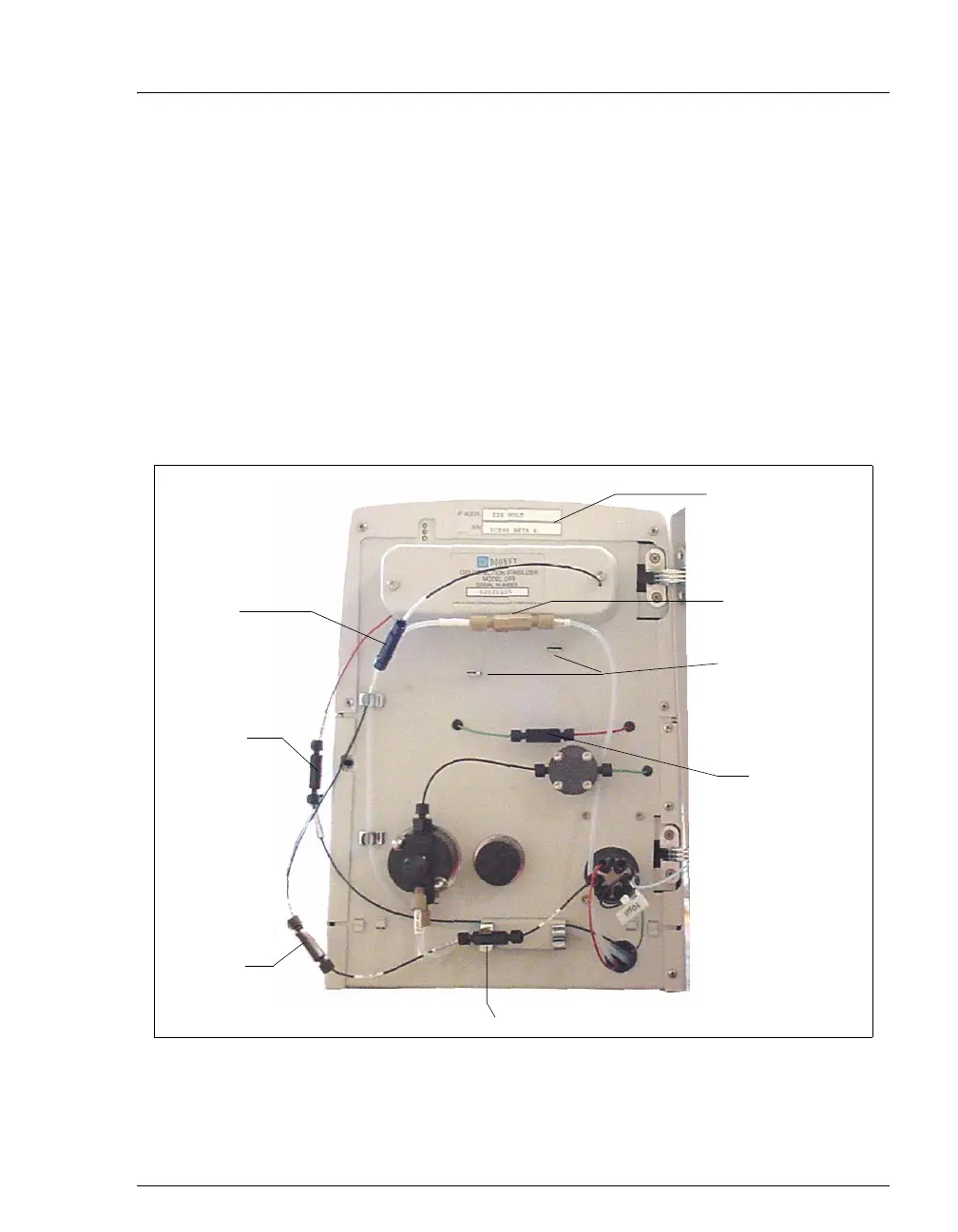
Figure B-19. ICS-90 Component Panel (Door not shown)
Column
In/Out
Union
(remove)
Suppressor
Brackets
Regen In/Out
Union (remove)
Eluent
In/Out
Union
(remove)
Guard In/Out Union (remove)
Serial Number
Cell Out
Union
Verify that 1
or 2 back-
pressure
coils are
installed (not
shown in
photo)
Do not
remove