Doc. 065215-02 9/09 101
C • TTL and Relay Control
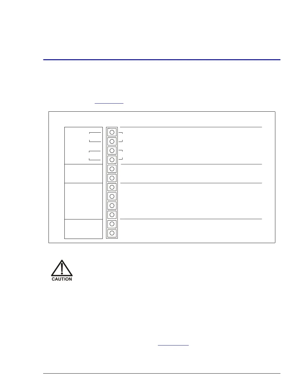
A 12-pin connector strip for TTL/relay control is located on the ICS-900 rear
panel. The connector provides two relay outputs, two TTL outputs, and four TTL
inputs (see Figure C-1
).
TTL and relay outputs can be used to control functions in external devices, such
as an autosampler or another Dionex module. Relay outputs 1 and 2 can be
programmed to switch any low-voltage control. Switched current must be less
than 200 mA and 60 V peak.
Relay outputs 1 and 2 can be configured to close when the pump flow is on and
open when the pump flow is off, thus ensuring that a connected device is turned
off when the pump flow is off. See Section C.3
for details.
Figure C-1. TTL and Relay Connector on Rear Panel
Relay loads in excess of 200 mA or with included power supplies over
60 V may damage the relay drivers on the instrument’s CPU board.
1
2
OUT
RELAY
(+)
TTL OUT
1
2
TTL GND
(-)
1
2
3
4
TTL IN
(+)
1
2
escr
pt
on
Solid State Relay Contacts Output
Pin Function
Solid State Relay Contacts Output
TTL Output 1 (1 k pull up to +5, 100 mA sink)
Ω
TTL Output 2 (1 k pull up to +5, 100 mA sink)
Ω
Ground
Ground
TTL Input 2
⎯
Inject/Load
TTL Input 3 Pump On/Off
⎯
TTL Input 4 Autozero
⎯
Note:
These are the
default TTL input
function assignments.
Functions can be
reassigned to any input.
TTL Input 1
⎯
Autozero