ICS-900 Operator’s Manual
18 Doc. 065215-02 9/09
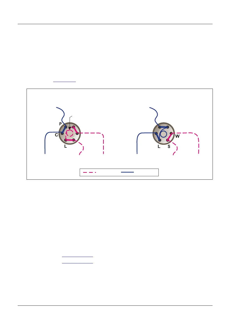
2.3.3 Injection Valve with Sample Loop
The injection valve is a six-port, electrically-activated Rheodyne valve. A
10 μL sample loop (P/N 042949) is installed on the valve at the factory.
The valve has two operating positions: Load and Inject. Eluent flows
through either the Load or Inject path, depending on the valve position.
Figure 2-6
shows flow schematics for the valve.
• In the Load position, sample is loaded into the sample loop, where it
is held until injection. Eluent flows from the pump, through the valve,
and to the column, bypassing the sample loop. Sample flows from the
syringe or autosampler line (if installed), through the valve, and into
the sample loop. Excess sample flows out to waste.
• In the Inject position, sample is swept to the column for analysis.
Eluent flows from the pump, through the sample loop, and on to the
column, carrying the contents of the sample loop with it.
Section 3.11.2
describes how to inject samples manually;
Section 3.11.3
describes how to inject samples with an autosampler.
Figure 2-6. Injection Valve Flow Schematics
L
AD P
ITI
NINJE
T P
ITI
N
= Sample
= Eluent
L
P
C
To Waste
Sample InTo Column
From Pump
Sample In
Sample Loop
To Column
To Waste
From Pump
L
S
W