ICS-900 Operator’s Manual
8 Doc. 065215-02 9/09
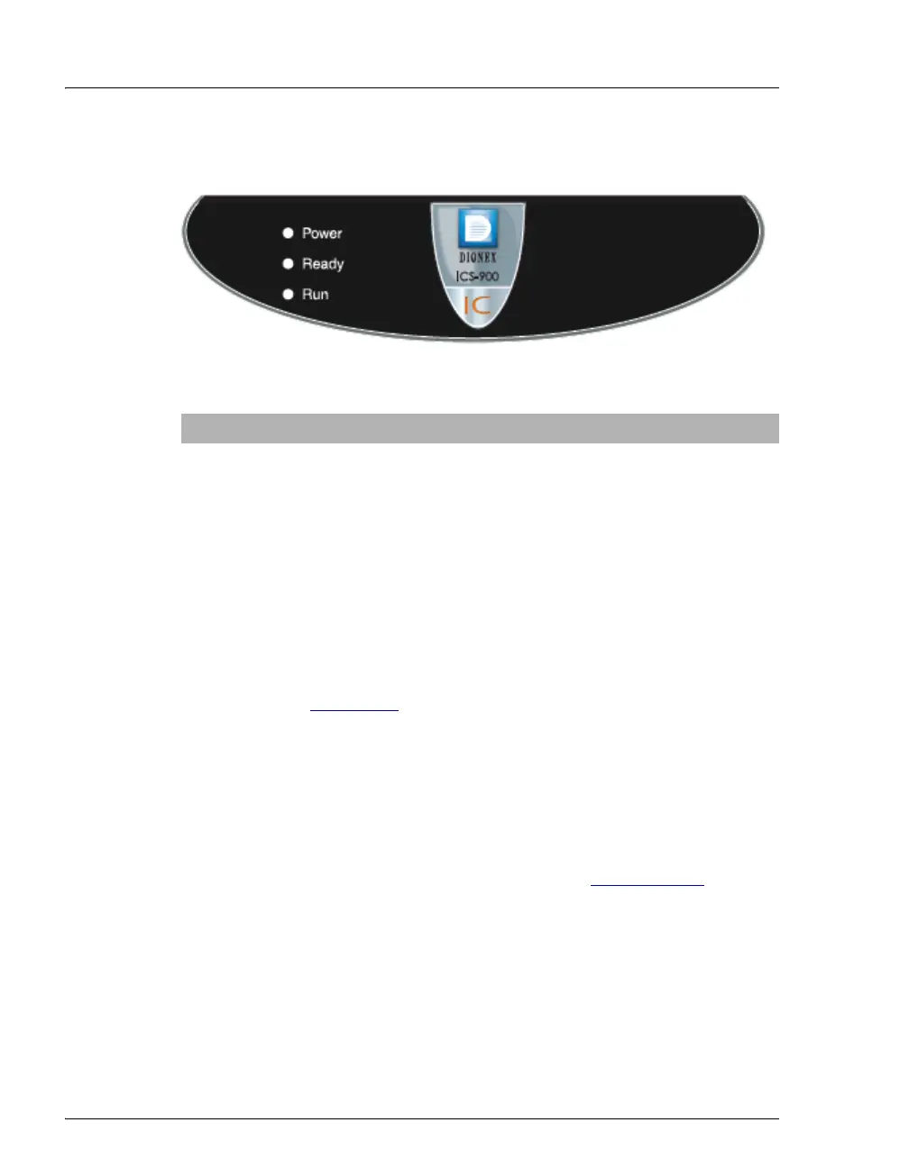
LEDs
Three status LEDs (described below) are on the ICS-900 front door.
Other status information and alarm messages are displayed in the Audit
Trail in Chromeleon or Chromeleon Xpress. For a description of these
messages, see Section 4.1
Injection Port
The injection port can be connected to the injection valve inside the
ICS-900. The sample to be analyzed is injected into the injection port
using a syringe. For automated sample injections, the ICS-900 injection
valve can be connected to an autosampler, instead of to the injection port.
For more information about sample injection, see Section 3.11.5
.
Eluent and Regenerant Bottles
The ICS-900 top cover is molded to hold one eluent bottle assembly
(P/N 062510) and one regenerant bottle assembly (anion, P/N 068222;
cation, P/N 068223).
• Eluent carries the sample through the ICS-900 and facilitates the ion
separation process. The type of eluent used depends on the analyses
LED Label If On (Green) If Flashing
Power ICS-900 power is on Does not flash
Ready System check passed, but
sequence not yet started
(LED stays on until run starts
or sequence is aborted)
System check failed (occurs if
system check executes for
10 minutes without success)
Run Running/acquiring data Error/alarm/fault (including
injection valve position)