Simga2N Traction Advanced Manual– V1.3 Page 30 (166) ©2021 DMC GmbH Herten Germany
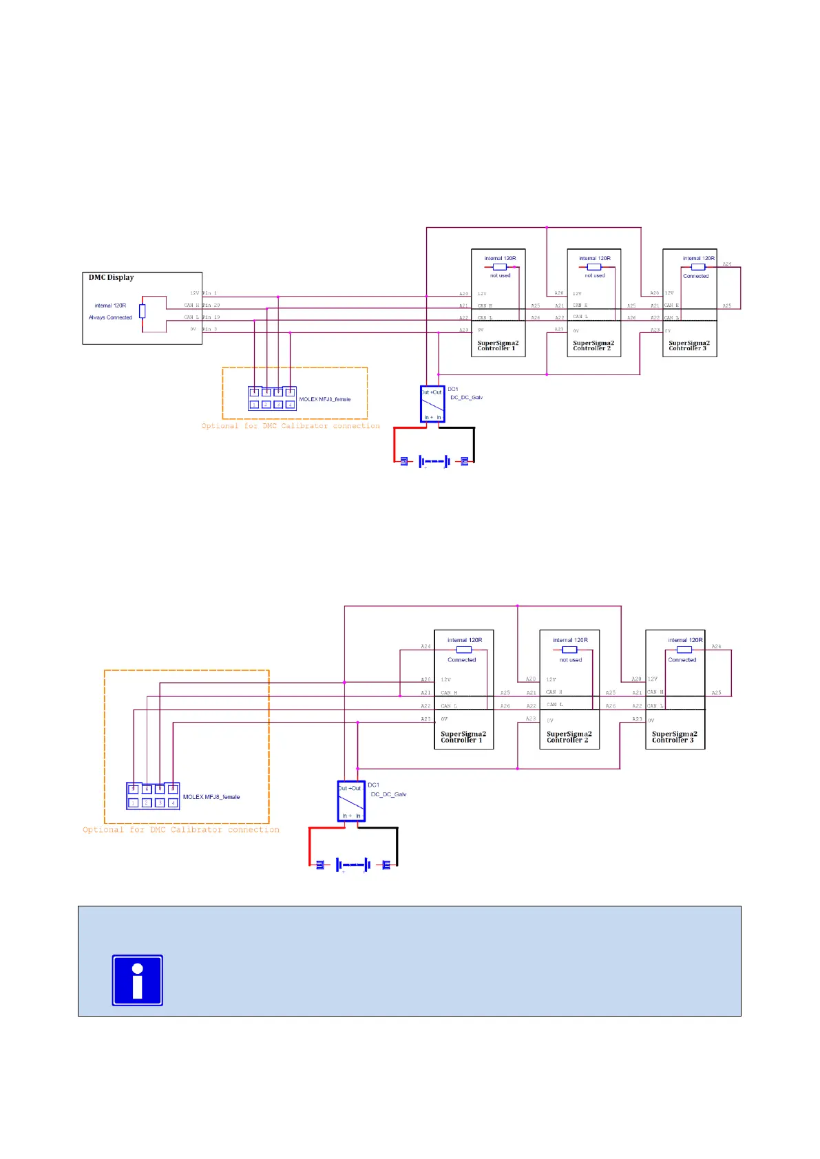
Isolated CAN bus wiring example with DMC Display:
The DMC Display and the DMC Colour Display have a CAN bus termination resistor installed. This resistor is fixed installed
and cannot be disconnected. The schematic below shows how the CAN bus termination should be wired when a DMC
Colour Display is part of the CAN bus installation and the CAN lines are isolated. The schematic also shows the optional
wiring of a 8-way female Molex Minifit connector which could be used to plug the DMC Calibrator. Mind that in this
case the DMC Calibrator cannot be plugged into DMC Simga2NConnector B - Communications - 8 Way (Molex Minifit).
Isolated CAN bus wiring example without DMC Display:
The schematic below shows how the CAN bus termination should be wired when no DMC Display is part of the CAN bus
installation and the CAN lines are isolated. The schematic also shows the optional wiring of a 8-way female Molex Minifit
connector which could be used to plug the DMC Calibrator. Mind that in this case the DMC Calibrator cannot be plugged
into DMC Simga2NConnector B - Communications - 8 Way (Molex Minifit).
In isolated-CAN version of the Simga2NController, when supplying the CAN bus with external
24V, pay attention when plugging the DMC Calibrator. Only DMC Calibrators later than serial
number D20340439 and without RS232 and Switch on the back can be supplied with more
than 12V.