Dobot CR A Series User Guide
Issue V1.3 (2023-09-14) User Guide Copyright © Yuejiang Technology Co., Ltd.
24
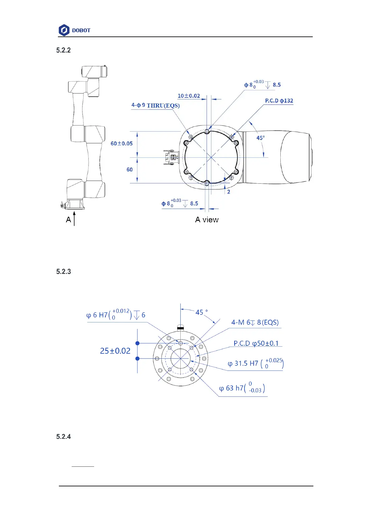
CR5A base installation dimensions
Figure 5.6 CR5A base installation dimensions
CR5A flange dimensions
The end flanges of CR A series robot arms (except CR20A) are all in the same size. The flange
design conforms to ISO 9409-1.
Figure 5.7 End flange dimensions
CR5A load curve
In the load curve, the coordinate origin is the center of the end flange, and X, Y represent the
distance between the gravity center of load and the robot flange in X and Y directions. According to
r =
√
𝑋
2
+ 𝑌
2
, the value r corresponds to the vertical coordinate X, Y[cm] of the load curve, and