Dobot CR A Series User Guide
Issue V1.3 (2023-09-14) User Guide Copyright © Yuejiang Technology Co., Ltd.
41
Electrical Features
Controller interface
Overview
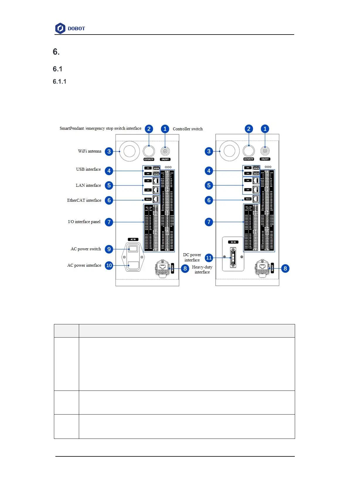
The electrical interfaces of the controller are all on the front side, as shown in the figure below.
The interface distribution of CC263 is basically the same as that of the CC262 AC model, with only
the power interface and switch modeling differing.
Figure 6.1 Controller electrical interfaces
Table 6.1 Interface panel description
Controller switch
After the controller is powered on, press the button for 0.5s and then release it, and
the controller will be turned on and the button turns blue.
When the controller is started, press the button for 3s and release it, and the controller
will be turned off and the robot arm will be powered off, and the blue light will be off.
SmartPendant and emergency stop switch interface
See 6.1.2 SmartPendant and emergency stop switch interface for details.
WiFi antenna
For connecting to PC or tablet through WiFi