Dobot CR A Series User Guide
Issue V1.3 (2023-09-14) User Guide Copyright © Yuejiang Technology Co., Ltd.
50
converts displacement into periodic electrical signals and then converts electrical signals into count
pluses, so that the displacements can be measured by the number of pulses. The input signal in a
specified format is supported.
This section takes OMRON E6B2-CWZ1X as an example to describe how to connect it.
According to different color cables of the encoder, connect each signal cable to the controller.
Connect the 5V power cable to I/O 5V, 0V power cable to I/O 0V, and then connect each coded
wiring in turn. If the ground wire is required, you can connect the cable shield to FG interface under
RS485 interface. There is no need to connect the ground wire unless in special circumstances (strong
magnetic interference, etc.).
Table 6.3 Wiring color
RS485 interface
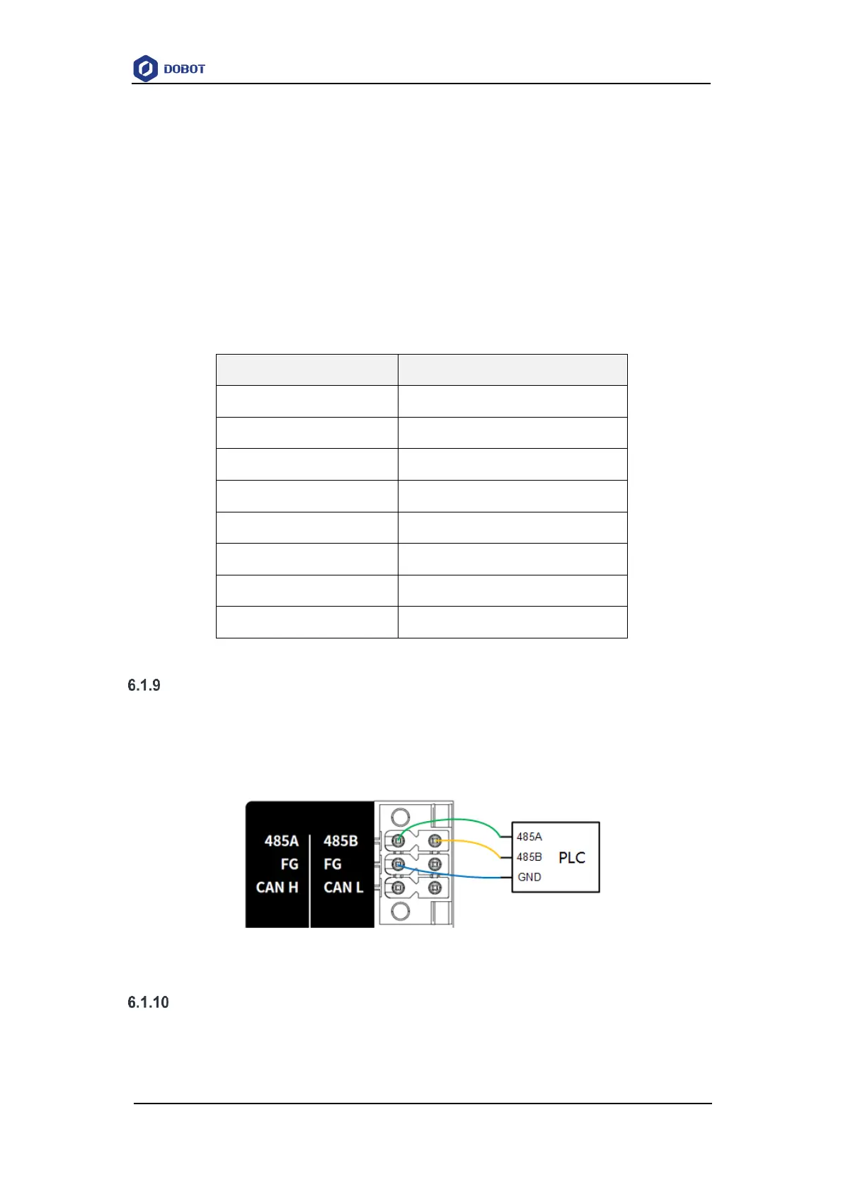
RS485 interface is mainly used for Modbus RTU communication. When connecting external
devices (such as PLC), connect the 485A (or 485+) and 485B (or 485-) interfaces of both devices
correspondingly, and connect the ground wire according to the actual condition, as shown below
(taking double-ended grounding as an example).
Figure 6.11 RS485 connected to PLC
Safety I/O interface
The safety I/O includes 20 interfaces: SI1~SI10, SO1~SO10.