Dobot CR A Series User Guide
Issue V1.3 (2023-09-14) User Guide Copyright © Yuejiang Technology Co., Ltd.
64
of the protective cover, refer to the diagram at the beginning of this section.
8. Install the protective cover to the controller, and fix it using 5 M3 screws delivered with
the protective cover.
Tool installation
The end flange of the robot arm has four M6 threaded holes, which can fix the tool to the end of the
robot arm. In order to accurately adjust the position of the tool, you can also use the reserved Φ6
positioning hole, and position it using pins. The end flanges of CR A series robot arms are all in the
same size. For detailed dimensions, refer to 5 Mechanical Specifications.
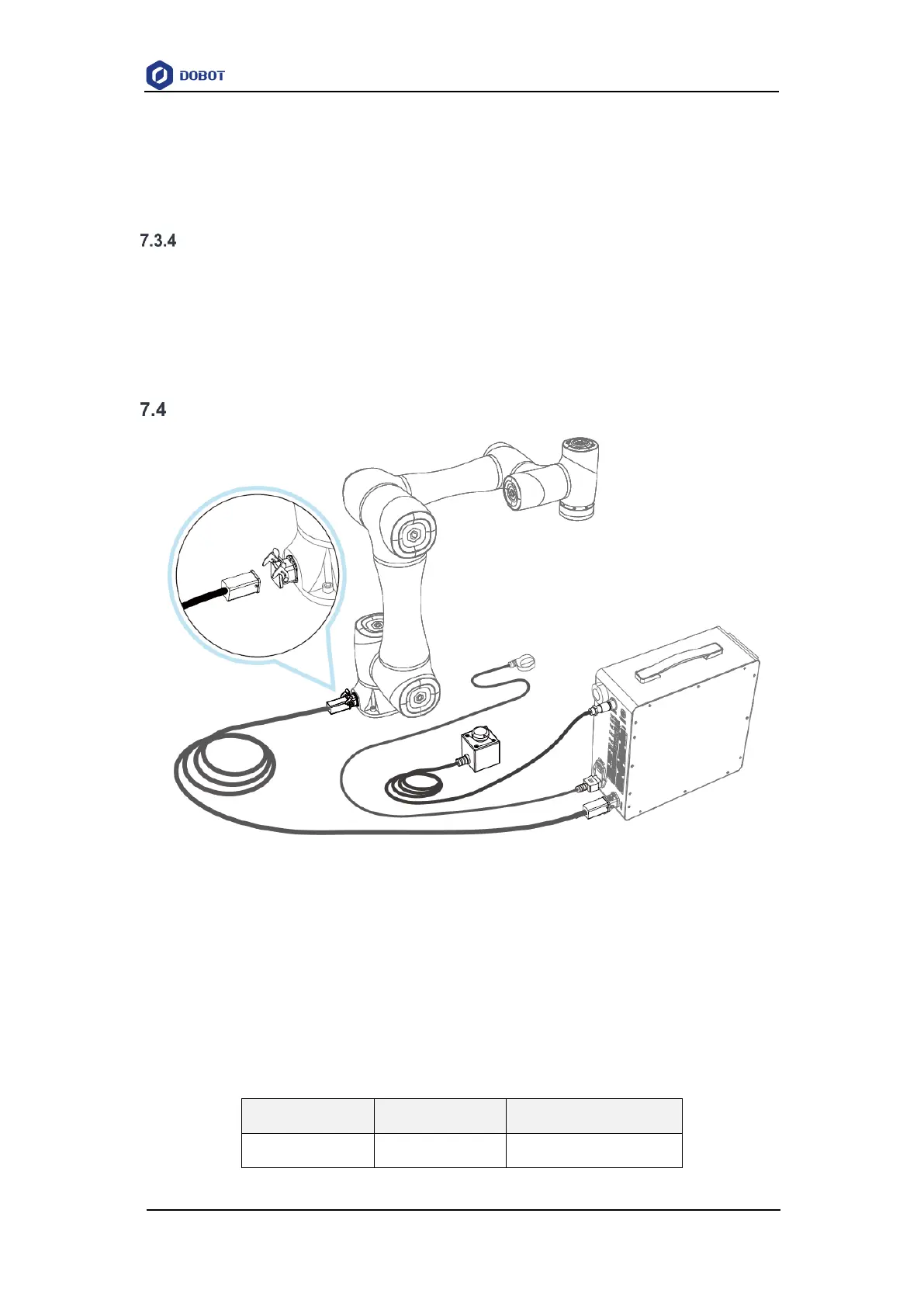
Wiring
Figure 7.1 Wiring diagram
1. Connect the controller to robot arm through a heavy-duty cable. When you plug the heavy-
duty connector into the heavy-duty socket, fasten the buckle of the heavy-duty connector.
2. Plug the emergency stop switch cable to the emergency stop switch interface. When
connecting, align the white dot on the connector with the white dot on the interface, and
rotate the blue plastic ring clockwise to fix.
3. Plug one end of the power cable into the power interface of the controller, and the other
end into main power socket. (For DC controller, connect other end to 48V DC power. See
the table below for terminal definitions).