Dobot CR A Series User Guide
Issue V1.3 (2023-09-14) User Guide Copyright © Yuejiang Technology Co., Ltd.
43
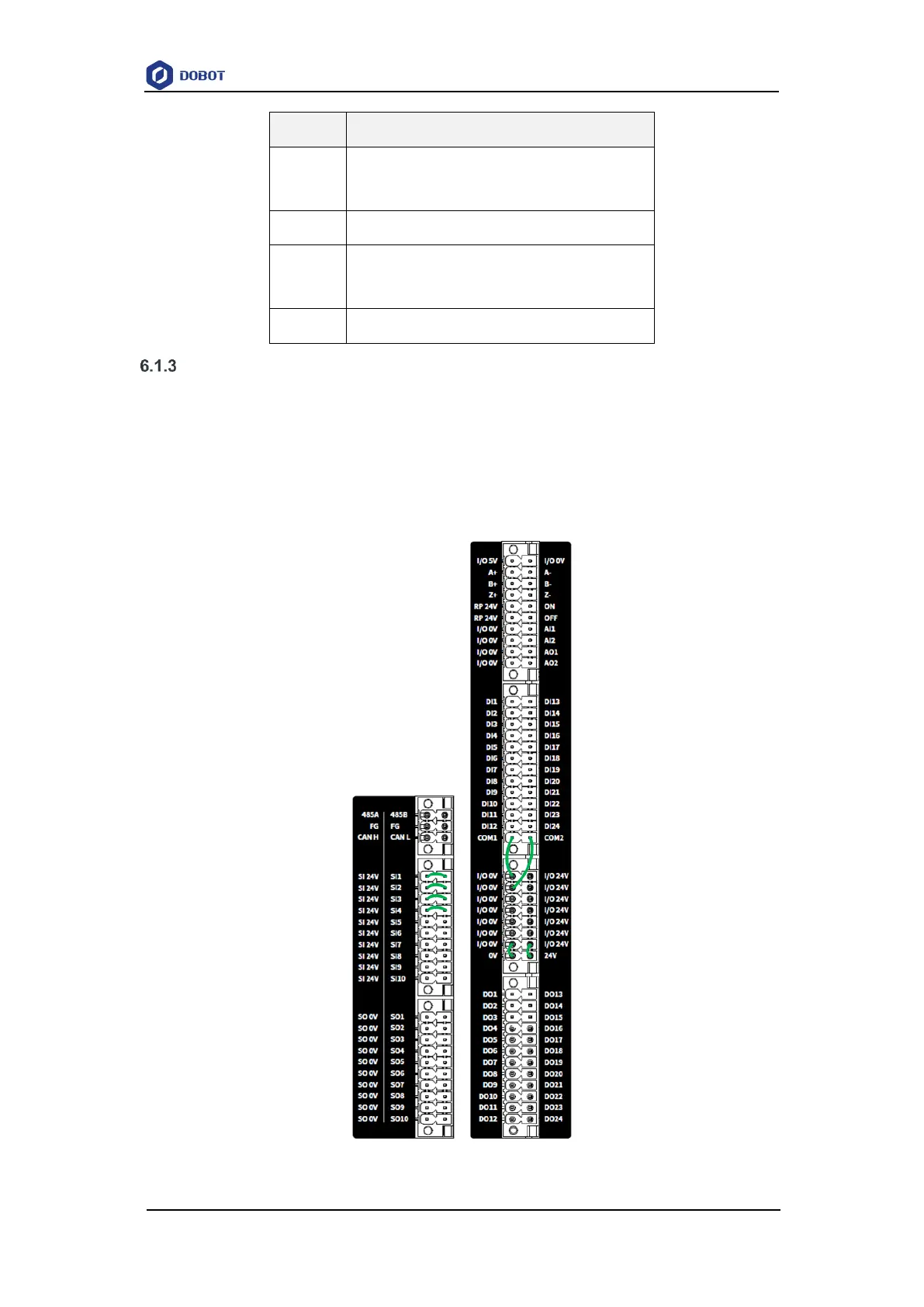
I/O interface panel
The robot controller contains an I/O interface panel for connecting to external equipment, such
as air pump, PLC, etc. The I/O interface panel provides 24 digital inputs, 24 digital outputs, 2 analog
outputs, 2 analog inputs, 1 incremental encoder input, 1 RS485 interface, 1 CAN interface, 10 safety
inputs and 10 safety outputs. All interfaces with the same screen have common functions. You
can select any available interface for wiring. The interfaces connected by the green lines in the
figure below are shorted by factory default.
Figure 6.2 Controller I/O interface