Dobot CR A Series User Guide
Issue V1.3 (2023-09-14) User Guide Copyright © Yuejiang Technology Co., Ltd.
44
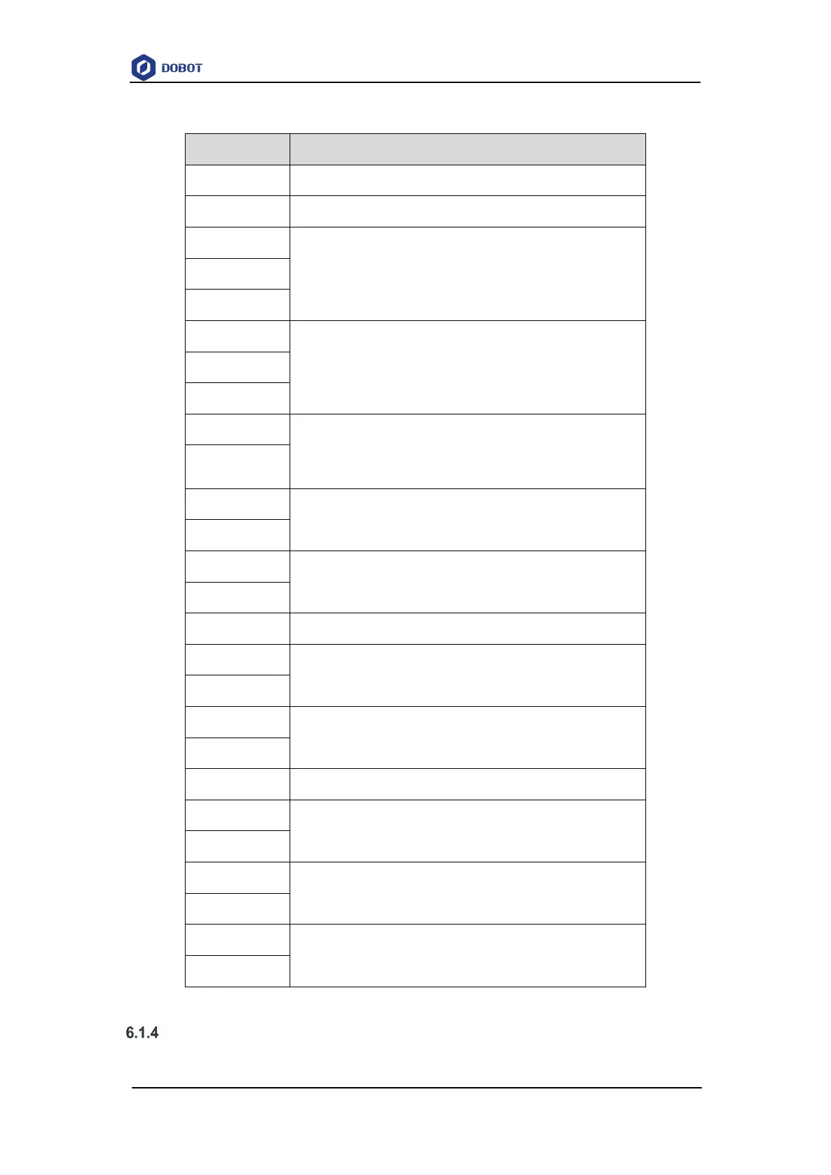
Table 6.2 Pin definition
Internal power source +5V
Pulse encoder interface. See 6.1.8 Encoder I/O interface
for details
Remote switch interface. See 6.1.7 Remote switch
interface for details
I/O power +24V and 0V Internal power supply or external
power supply can be realized through different wirings.
See 6.1.4I/O interface power for details
Analog input/output interface. See 6.1.6 Analog I/O
interface for details.
Digital input/output interface. See 6.1.5 Digital I/O
interface for details
DI common ground for switching types of DI signal.
Internal power source +24V and 0V
RS485 interface. See 6.1.9 RS485 interface for details
For encoder, 485 and CAN grounding
CAN bus interface (reserved)
Safety I/O power +24V and 0V
Safety input/output interface. See 6.1.10 Safety I/O
interface for details