Dobot CR A Series User Guide
Issue V1.3 (2023-09-14) User Guide Copyright © Yuejiang Technology Co., Ltd.
45
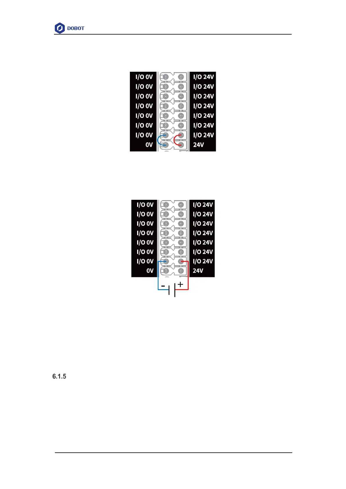
The I/O interface can be powered by internal and external 24V power supply, with a maximum
of 500mA for each DO and a total output current of 3A. When using the internal power supply, short
circuit 0V and 24V with the nearest I/O 0V and I/O 24V, as shown below.
Figure 6.1 I/O connected to internal power supply
If a larger total output current (maximum 5A) is required, you can connect a 24V (±2%) power
supply, as shown below. The external power supply and internal power supply are isolated and do
not interfere with each other.
Figure 6.2 I/O connected to external power source
NOTE
The subsequent sections are based on the prerequisite that the I/O power supply has been
connected, and will not describe I/O power supply wirings.
Digital I/O interface
The DI interface must be connected to the COM interface, and can switch signal types (PNP
or NPN) through the COM interface. COM1 is used with DI1~DI2, and COM2 is used with
DI13~DI24.
The wiring of DI connected to a simple switch is shown below. (left figure: PNP wiring, right
figure: NPN wiring)