Dobot CR A Series User Guide
Issue V1.3 (2023-09-14) User Guide Copyright © Yuejiang Technology Co., Ltd.
60
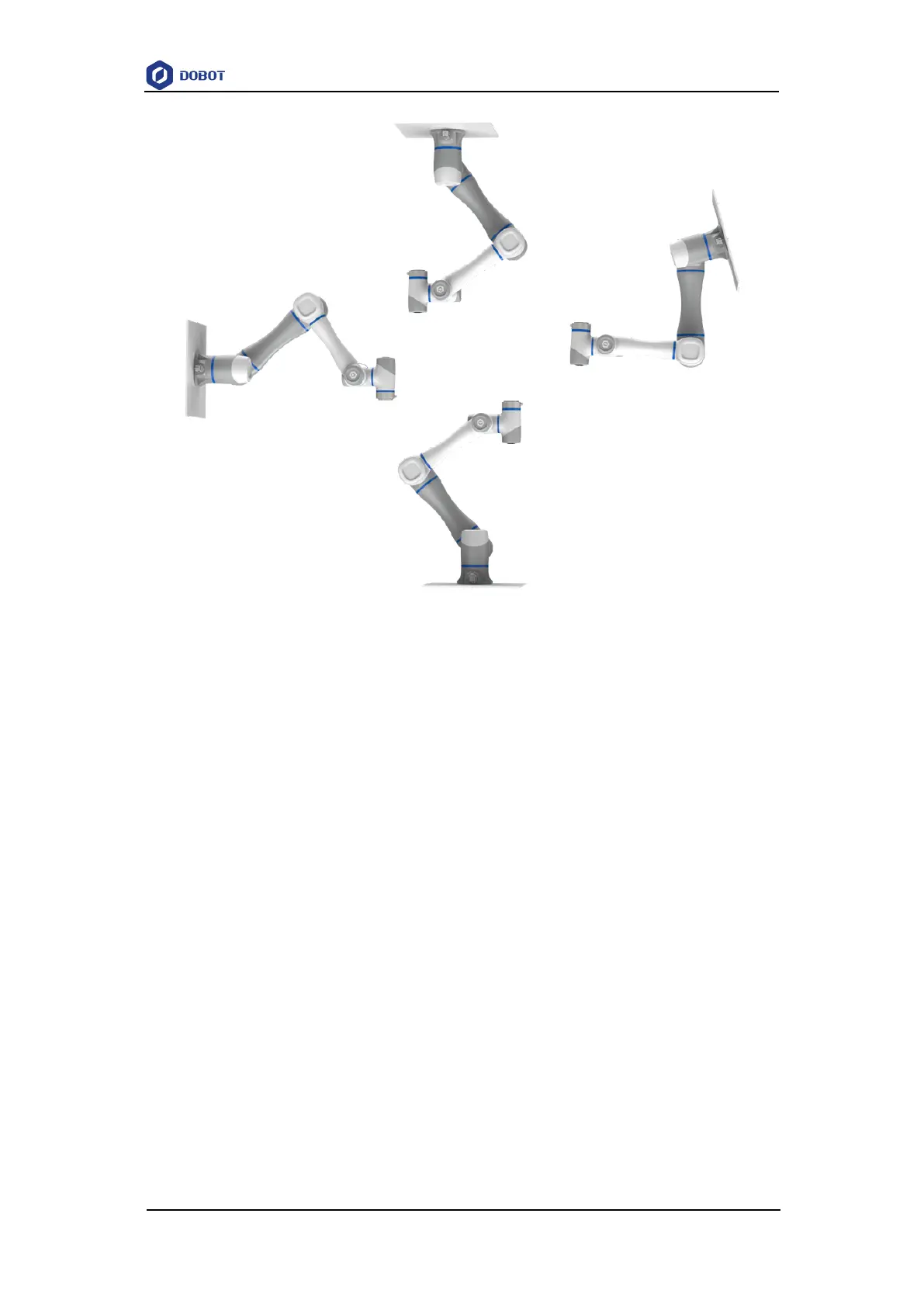
Figure 7.1 CR A robot installation posture
When installing the robot arm, position the mounting holes on the installation platform
according to the installation size of the robot base. Fix the robot arm base on the platform using
bolts. Be sure to observe the following during installation.
When the robot is transported, ensure that the robot is stable and kept in proper place.
When the robot is hoisted (CR20A comes with its own sling from the factory, if other
models need to be lifted, users are requested to provide their own sling), be sure to take
appropriate measures to locate the moving parts so as not to cause accidental movement
and harm during hoisting and transportation.
When moving the robot from the packing box to the mounting position, hold the robot
until all bolts on the robot base are fastened.
When the robot is installed, take corresponding measures to locate it. Be sure to use hex
bolts (ISO898-1: 2013, property class: 12.9) to fix and tighten the robot base. The CR3A
requires the use of 4 M6 bolts, the CR20A uses 6 M10 bolts, and the other models use 4
M8 bolts
When the robot is installed on the wall or upside down, be sure to take the anti-fall
measures of the robot base.
The installation platform of the robot arm should be stable enough to withstand at least
10 times the maximum torque of the J1 joint, and at least 5 times the weight of the robot
arm.
If the robot arm is installed on a linear axis or a moving platform, the acceleration of the
platform should be low. High acceleration may trigger the collision detection mechanism